
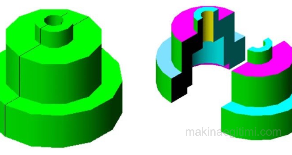
In this article we cover the types of sectioning in technical drawing and the sectioning methods available. We will look at topics such as full section, half section, partial section, and revolved section. For another article of ours with the basics of sectioning, see: Sectioning in technical drawing
Types of Sectioning
The types of sectioning used in technical drawing vary depending on the shape of the part to be manufactured. For some parts we need to section the entire part (full section), while for others we may want to show both the outer and inner appearance at once (half section). Sometimes, in special cases, we may need to show only a specific region as a section (partial section). In some cases our cutting plane may not be a straight line (offset section).
Now let’s look at all of these sectioning methods and how they are done.
Full Section

The full section method is a type of section thought of as cutting the part parallel to its axis and dividing it in two through the middle; it fully describes the internal features of the part.

Let’s imagine we have a cylindrical part with holes in it, as shown above. When we look at the front view of this part, we show the hidden holes in the drawing with dashed lines. Although this may not seem like a problem for this particular part, in more complex parts the dashed lines will overlap each other, making it very hard to visualize the part in our minds. That’s why it’s best to use sectioning for this type of part.
How Is a Full Section Made?

In the full sectioning process, we imagine a cutting plane assumed to divide the part exactly in two through the middle. We set one of the resulting pieces aside and consider only the regions the cutting plane intersects on the other piece.

In the full sectioning process, we apply hatching to the regions where the cutting plane touches the part as it divides it. (above)
See related topic: Hatching Lines in Technical Drawing

Finally, we mark where the cutting plane passes in our drawing with the letters A-A, and the full sectioning process is complete.

In regular view drawings, internal features are shown as invisible using dashed lines, while with a full section the dashed lines are removed and drawn instead as thick continuous lines. Above, we see the sectioned and unsectioned drawings of the same part side by side.
Half Section
Also called a 1/4 section. It is a type of section thought of as cutting away one quarter of the part. In the sectioned view, half of the part shows its interior while the other half shows its exterior appearance.
Let’s see how a half section is made with an example:

Let’s imagine passing a two-part cutting plane from top to bottom in a way that separates one quarter of the part.

After separating and discarding the quarter piece, let’s look at the part from two different directions as shown above. To the left of the axis we draw the exterior view of the part, and to the right of the axis we draw the interior view of the part. (above)

Three different technical drawings of the same part: unsectioned, fully sectioned, and half sectioned. (above)
You can download the 2D and 3D drawings of the part used in this example.


In some cases, half sections may have angular edges or ridges that fall right on the axis, both inside and outside the part. In such cases, these edges are drawn as continuous thick lines. (figure above)

Partial Section (Local Section)
Also called a local section. These are sections covering a smaller region than a half section, drawn as if a piece were torn away, without needing to draw a full or half section.

It describes the interior of the sectioned region and provides information about the internal structure of the part. The area treated as torn away is drawn with a continuous thin freehand line.
Offset Section
This is the type of section taken in order to represent non-symmetrical parts in a single view.

To be able to show all the details of the part, the cutting plane is passed through it in a stepped, offset manner.

The contact regions marked in red in the picture above, where the cutting plane passes, are shown with hatching in the production drawing.

The regions the cutting plane passes through are indicated in the production drawing with the letters A-A. The turning points of the section are indicated with a thick line. There is no need to letter the turning points.

When drawings are complex, it is helpful to add letters. Such sections are also called sections taken through two or more parallel or successive planes. In some cases, the turning points of a part’s section may not be at 90°.
Revolved Section
Non-symmetrical, angular parts are rotated until they come into a position parallel to the axis. Then the section is taken as if it were a full section.

When we want to show this type of part as a section, we cannot choose the full section or half section methods. To give the manufacturer all the information needed for production, we need to show all the details of the part fully dimensioned.

For this reason, we split the part into two as shown above.

Pay attention to the regions separated by the cutting plane. This way we can show all the details of the part fully dimensioned for manufacturing.

In the part’s production drawing, in the top view, we take the details on the second axis, treat the first axis as the reference, and shift them by rotating.

During the rotation, a compass is anchored at the center point “O.” All edges and corner points are rotated until they come into a position parallel to the axis. Then, from these points brought onto the axis, perpendicular projection lines are carried over to the new view to obtain the view.

Example of a revolved section (above)
Related Posts
 Choosing Tolerance Zones and Fits
 Geometric Drawings 2 – Dividing Circles
 International Projection Standards ISO-E and ISO-A
 What Is Tolerance? Tolerances Lesson 1
 What Does a T-Square Do, How Is It Used?
 Showing Dimensional Tolerances in Technical Drawing
 How Is Getting Views Done
 How to Draw an Ellipse? Ellipse Construction.