

As a machine education site, in this article in our Machine Technical Drawing section, we’ll cover how dimensional tolerances are shown in technical drawing. How are dimensional tolerances shown with symbols or numbers? How are the tolerances of mating parts shown? We’ll also cover topics like showing tolerances in a table.
Showing Tolerances for Linear Dimensions
Let’s go through how tolerances for linear dimensions are shown in technical drawing, in a few steps.
Showing Tolerances with Symbols

Next to the basic dimension on the dimension line for the section to be toleranced, either the tolerance symbol is placed as shown on the upper left, or, as shown in the figure on the right, the deviation values are given in parentheses in mm after the symbol. The deviation value digits should be written smaller than the basic dimension digits, with the upper deviation value on top and the lower deviation value on the bottom.
Showing Tolerances with Numbers

The tolerance’s deviation values are written directly next to the basic dimension, in smaller-sized digits, with the upper value on top, in mm. If one of the deviation values is zero, it should be shown with the digit zero. (figure above)
Showing Symmetric Tolerances

If the absolute values of the tolerance’s deviations are equal to each other, the deviation value should be indicated with a single number written after the ± sign next to the basic dimension.
Showing Dimension Limits

Of the tolerance’s deviation values, the positive one can be added to the basic dimension and written on top as the maximum dimension; the negative one can be subtracted from the basic dimension and written at the bottom as the minimum dimension. In the figure above, the dimension limits are shown for a dimension with a basic size of 30 mm and deviations of +0.1 and -0.1.
Showing a Dimension Limited in One Direction

If a dimension only needs to be limited in one direction, this dimension should be shown with either the min or max marking.
Showing Tolerances for Mating Parts
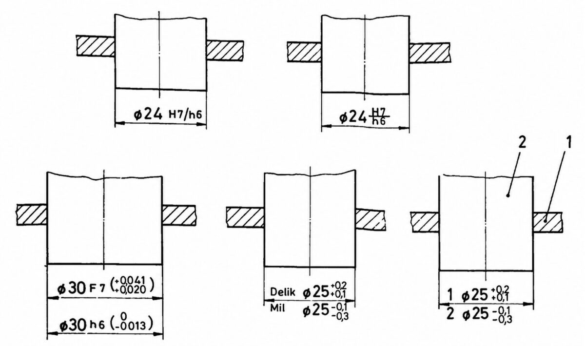
To indicate the tolerances of mating female and male parts, this should be applied as shown in the figure above. In such representations, the hole’s dimension should be written above the shaft’s dimension.
Showing Tolerances in a Table

If there isn’t enough room on the drawing to write the tolerance values, or if a great many tolerances need to be shown, the tolerance values can be given via a table drawn in a suitable place on the drawing sheet, as shown in the figure above. Doing this avoids a lot of complex markings, makes the drawing simpler and more understandable, saves time, and helps prevent mistakes. On the drawing, the tolerance values of the relevant dimensions are shown with symbols, and the table gives the numerical values or dimension limits for these symbols.
Dimensions Without a Specified Tolerance
In principle, tolerances should be indicated on all dimensions in machine drawings. However, for dimensions that aren’t related to fits and don’t require a special degree of accuracy, the tolerance is specified only once, in a simple note, under the heading “tolerances to be applied to dimensions without a specified tolerance.”

The figure above gives the permitted deviations for linear dimensions according to machining grade. These deviations give the tolerances to be applied to dimensions without a specified tolerance.
Related Posts
 What Is Perspective. Types of Perspective and Exercises
 Dimensioned Isometric Drawing Examples – Part 2
 Choosing Tolerance Zones and Fits
 Geometric Drawings 1 – Dividing Lines and Erecting Perpendiculars
 Dimensioned Isometric Drawing Examples – Part 1
 How to Draw an Ellipse? Ellipse Construction.
 Specifying the Manufacturing Method by Surface Roughness
 Fit Tolerances and Tolerance Pairs – Lesson 3