
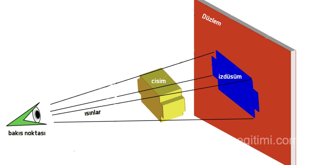
In Turkey and European countries, the ISO-E projection method is used. However, within the technological relationships between countries, it’s also necessary to know the ISO-A projection method.
ISO-E (ISO-Europe): Used by Europe and the countries we’re aligned with.
ISO-A (ISO-America): Used by the United States and the countries aligned with Britain.


Getting Views According to the ISO-E Projection Standard
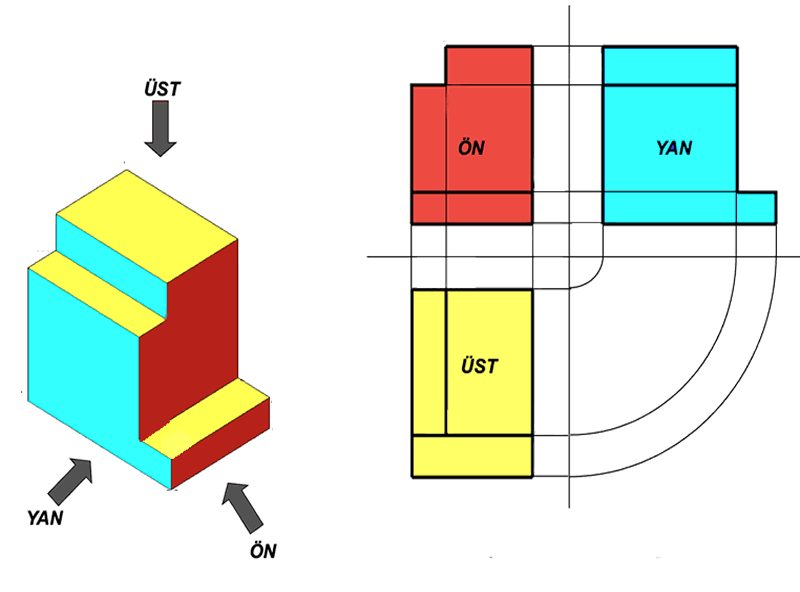

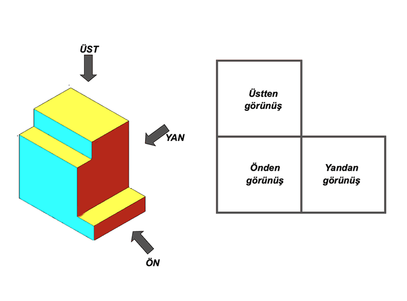
ISO-E (Third-Angle) Method
In the ISO-E projection method, the view placed to the right of the front view shows the part’s right side face (“third-angle” projection).
ISO-A (First-Angle) Method
In the ISO-A method, the view placed to the right of the front view shows the part’s left side face (“first-angle” projection).
Identifying by Symbol
Which projection method is used in a technical drawing is indicated by a standard cone symbol in the corner of the drawing sheet.
Getting Views According to the ISO-A Projection Standard
Especially those of you using SolidWorks will know this. You’ll have run into it when getting views from a solid model. The top view is placed on top, and the side view reflects a view from the right, not from the left.

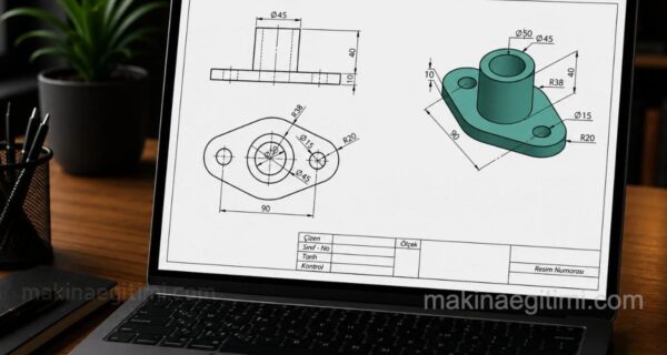
ISO-E Getting-Views Sample Exercises

EXERCISE -2
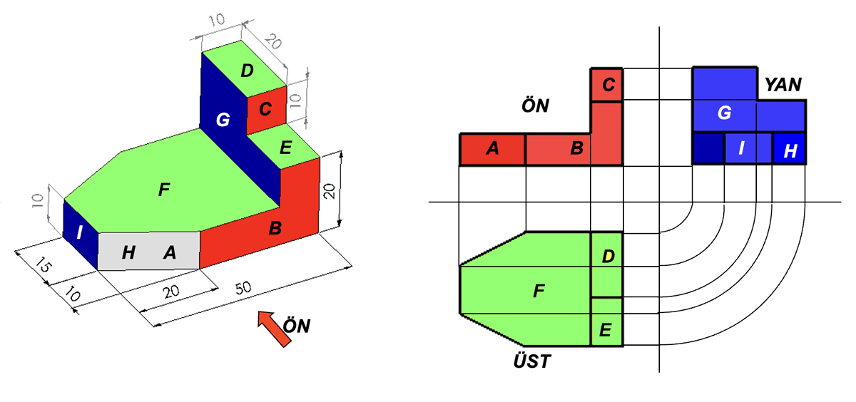
EXERCISE –3

Related Questions
In both methods, views are obtained in a similar way, but the view placed to the right of the front view shows a different face. In ISO-E, this is the part’s right face; in ISO-A, it’s the left face.
There’s a standard cone symbol in the corner of the drawing sheet. The shape of this symbol shows whether the drawing was made using the ISO-E or ISO-A method.
Related Posts
 Dimensioned Isometric Drawing Examples – Part 1
  Technical Drawing View Extraction Examples 1
  Dimensioned Isometric Drawing Examples – Part 3 How Is Dimensioning Done? Rules of Dimensioning
  Technical Drawing View Extraction Examples 2
  Showing Specially Treated Surfaces in a Drawing
  Technical Drawing Paper Sizes and Folding
  Geometric Drawings 2 – Dividing Circles