Close Menu
  • MAKİNELER ve İMALAT
    • Tools & Equipment
    • Computer-Aided Drawing
    • CAD/CAM Education
    • CNC Machine Programming
    • Casting Technologies
    • Electrical & Electronics Technologies
    • Hydraulics & Pneumatics
    • Manufacturing Processes
    • Manufacturing Technologies
    • Occupational Safety
    • Mold & Die Design
    • Solid Modeling
    • Welding Technology
    • Machine Elements
    • Mechanical Trade Drawing
    • Materials Science
    • Automotive & Vehicle Technologies
    • Robotics Technologies
    • Health Technologies
    • Defense & Aerospace Technologies
    • Descriptive Geometry
    • Technical Drawing
    • Software & Hardware Technologies
    • Innovative Manufacturing Methods
  • TEKNOLOJİ ve YAŞAM
    • OTOMOBİLLER ve TAŞIT
      • Vehicle & Engine Knowledge
      • Safe Driving
      • Sürüş Destek Sistemleri
    • Genel Kültür
      • Movies & TV Shows
      • Görsel ve Grafik Sanat
      • Books & Literature
      • Music
      • Sports
      • History
      • History of Technology
    • GÜNDELİK YAŞAM TEKNOLOJİLERİ
    • Hobbies & Entertainment
    • Internet Technologies
    • Health
    • Mobile Technologies
Makine Eğitimi
  • Machines & Manufacturing
    Machine Elements
    Hydraulics & Pneumatics
    Technical Drawing
    Computer-Aided Design & Manufacturing
    Basic Manufacturing Processes
    Manufacturing Processes
    Industry Technologies
    Other Technical Courses
    Motion & Power Transmission
    Simple Machines
    Chains & Sprockets
    Shafts & Journals
    Gears
    Cams
    Couplings
    Belts & Pulleys
    Springs
    Bearings
    Keys
    Fastening Joining
    Retaining Rings
    Screws, Bolts & Nuts
    Cotter Pins
    Flanges
    Welding
    Rivets
    Pins & Bolts
    Washers
    Calculators
    Gear Ratio Calculator
    Spring Constant Calculator
    Belt Pulley Ratio Calculator
    Other Machine Elements
    Slides & Linear Guides
    Brakes
    Flywheels
    Clamps
    Shock Absorbers
    Gaskets & O-Rings
    Seals & Sealing Elements
    Hydraulics
    Introduction to Hydraulics & Principles
    Hydraulic Systems & Applications
    Accumulators
    Filters
    Motors
    Pumps
    Valves
    Pneumatics
    Introduction to Pneumatics & Principles
    Pneumatic Systems & Applications
    Pneumatic Circuit Components
    Valves
    Cylinders
    Silencers
    Motors
    Compressors
    Dryers
    Conditioning Units
    Common Topics & Maintenance
    Hydraulic & Pneumatic Maintenance
    Study Notes, Exams & Tests
    Technical Drawing
    Introduction to Technical Drawing
    Geometric Drawings
    Perspective & Projection
    Orthographic Views
    Dimensioning
    Sectioning
    Assembly & Detail Drawings
    Tolerances
    Surface Finish Symbols
    Mechanical Engineering Drawing
    Screws, Bolts & Nuts
    Pulley Drawings
    Gear Drawings
    Shafts & Journals
    Bearing Drawings
    Pins & Bolts
    Spring Drawings
    Welds in Technical Drawing
    Washers
    Cotter Pins
    Technical Drawing Exercises
    Mechanical Drawing Exercises
    Gear Exercises
    View Extraction Exercises
    Pulley Exercises
    Pin & Bolt Exercises
    Threaded Fastening Exercises
    Descriptive Geometry
    Computer-Aided Drawing
    AutoCAD Drawing Lessons
    Computer-Aided Drawing Exams
    Solid Modeling & Animation
    Solid Model Drawing Files
    Solid Model Assembly Examples
    Solid Model Drawing Lessons
    3D CAD Software Reviews
    Solid Modeling Exercises
    CNC Programming
    CAM
    Measurement & Inspection
    Dial Indicators
    Calipers
    Gauges
    Micrometers
    Materials Science
    Steels
    Cast Iron
    Aluminum
    Plastics
    Material Testing & Hardness Measurement
    Occupational Safety
    Workshop Safety
    Safety When Working With Electricity
    Machine Safety Rules
    Hand Operations
    Filing
    Marking
    Cutting Operations
    Reaming
    Tapping
    Threading With a Die
    Drill Bit Sharpening
    Working With Machines
    Basic Turning Operations
    Basic Milling Operations
    Shaper Machine
    Machining
    Turning
    Milling
    Grinding
    Innovative Manufacturing Methods
    EDM (Electrical Discharge Machining)
    Laser Machining
    Waterjet Machining
    3D Printing
    3D Scanners
    Welding
    Rolling
    Casting
    Mold & Die Design
    Mechanical & Hydraulic Presses
    Blanking & Piercing Dies
    Bending Dies
    Drawing Dies
    Plastic Injection Molds
    Extrusion Dies
    Compound Dies
    Progressive Dies
    Blow Molds
    Spinning Dies
    Spray Molds
    Manufacturing of Machine Parts
    Automotive & Vehicle Technologies
    Motor Vehicle Manufacturing
    Raw Material Production
    History of Technology
    Health & Medical Technologies
    Defense & Aerospace
    Robotics Technologies
    Software & Hardware Technologies
    Mechanics - Strength of Materials
    Physics Topics
  • Technology & Life
    Hobbies & Entertainment
    Sports
    Music
    Vehicle & Engine Knowledge
    Vehicle Maintenance & Repair
    Safe Driving
    Driver Assistance Systems
    History
    Movies & TV Shows
    Books & Literature
    Computers & Internet
    Computer Tips
    Software Reviews
    Hardware & Peripherals
    Practical & Safe Internet Use
    Visual & Graphic Art
    Mobile Technologies
    Travel
    Science
    Health
    First Aid Knowledge
    Everyday Technologies
Makine Eğitimi
Home»Physics Topics»Simple Machines
29 August 2026

Simple Machines

Simple Machines

Physics lesson: Simple Machines. Article contents and topics:

  • Properties of Simple Machines
  • What Are Simple Machines?
    • Levers
      • Types of Levers and Everyday Examples
    • Pulleys
      • Fixed Pulleys
      • Movable Pulleys
      • Block and Tackle
    • Inclined Plane
    • Gears
    • Pulleys (Belt Pulleys)
  • Related Questions

Machines made of very few parts, which only use a single type of force, are called simple machines. Simple machines can be found in many places in everyday life.

prybar force

In the picture above, force can be applied to the prybar in the directions shown by the numbered arrows. In which direction should force be applied to pull the nail out of the board more easily?

scissors bottle opener pliers force

In everyday life, we use many tools built by taking advantage of changing the direction of a force. These tools make it easier for us to do work.

The purpose of simple machines is to make doing work easier by changing the magnitude and direction of the applied force.

Properties of Simple Machines

  • They make work easier. However, there is no gain or loss in the work itself. As a result of the work, they don’t produce any gain or loss in energy either. They also don’t save energy.
  • Simple machines allow the direction, magnitude, and point of application of a force to be changed.
  • There is a gain in either force or distance. However, both gains cannot be achieved at the same time.
  • Energy must always be used when work is done with a simple machine.

A gain in force in a simple machine happens because the input force is smaller than the output force. In other words, tasks that require a large force can be done with a small force.

Lever Principle


Levers change the effort arm relative to the fulcrum, allowing heavy loads to be moved with little force.

Inclined Plane Advantage


An inclined plane lets you move a load along a longer path that requires less force, instead of lifting it directly.

Pulley Systems


When fixed and movable pulleys are used together, the pulling force needed can be reduced depending on the number of pulleys.

What Are Simple Machines?

Levers

A lever is a device consisting of a sturdy rod that can rotate about a fulcrum point.

force load lever

In a lever, the distance from the force to the fulcrum is called the effort arm, and the distance from the load to the fulcrum is called the load arm.

force load effort arm lever

In levers
the relationship: force x effort arm = load x load arm applies.


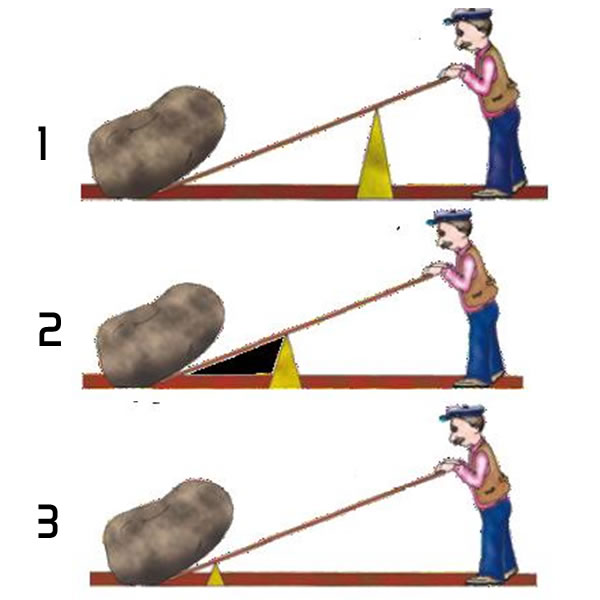
The longer the effort arm is compared to the load arm, the greater the mechanical advantage in force.

The farther the applied force is from the fulcrum, the smaller it needs to be; if the load is close to the fulcrum, less force needs to be applied; if the applied force is close to the fulcrum, it needs to be greater.

In the figure alongside, the worker applies the greatest force in position 1, and the least force in position 3.
simple machines lever

Types of Levers and Everyday Examples

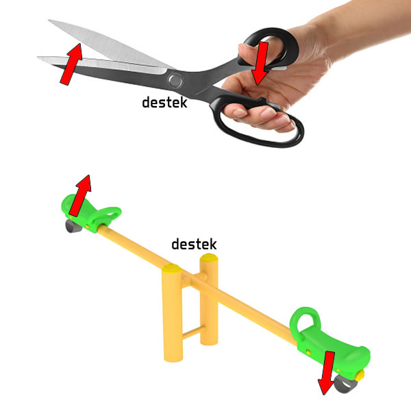
We can say there are different types of levers depending on the position of the fulcrum and the applied force. Simple machines have more uses in our lives than you might think.
types of levers scissors seesaw

TYPE 1: Simple machines that work on the lever principle with the fulcrum in the middle include examples such as pliers, scissors, seesaws, tongs, crowbars, and equal-arm balance scales.

uses of simple machines types of levers

TYPE 2: The fulcrum is at one end, the force at the other. Simple machines that work on this lever principle include examples such as a nutcracker, a wheelbarrow, and a bottle opener.
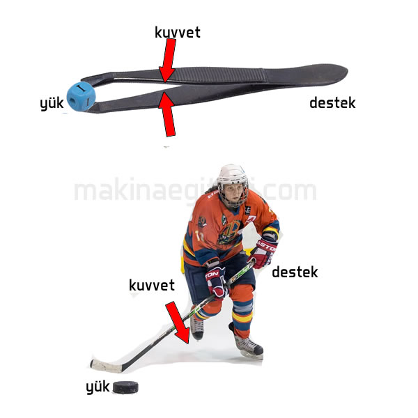
simple machines forces types of levers

TYPE 3: The applied force is between the fulcrum and the load. For example: a tennis racket, tweezers, an oar, tongs, a forearm muscle, a hockey stick, etc.

Archimedes and his saying about the lever

The saying of Archimedes, the inventor of the lever, about the lever expresses to us the magnitude of the mechanical advantage a lever can provide.

Pulleys

Pulleys are among the devices we can call simple machines. They are simple machines that can rotate freely around a fixed axle and have a groove around their circumference for a rope to pass through.

Fixed Pulleys

A pulley hung from a fixed point that rotates to make it easier to move objects is called a fixed pulley.

The object can only be lifted with a force equal to its own weight. There is no gain in force.

It only makes work easier by changing the direction and line of action of the force.

simple machines fixed pulley

Movable Pulleys

These are pulleys that move together with the load attached to the pulley’s axis of rotation.

These pulleys provide a gain in force. For example, in the pulley system shown in the figure, if the load is 100 kg, we can lift the load with a force of 50 kg.
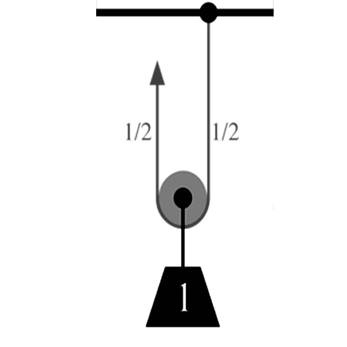
simple machine movable pulley

Block and Tackle

This is a system of pulleys made up of fixed and movable pulleys, intended to provide a gain in force.

This gain depends on the number of rope strands passing through the movable pulleys that make up the block and tackle. In the figure, the system on the left has a force gain of 1/2, while the system on the right has a force gain of 1/4.

simple machines block and tackle

Inclined Plane

inclined plane, one of the simple machine topics

These are simple machines that provide a gain in force by lengthening the distance traveled.

On an inclined plane, the force travels a distance equal to the length of the incline, while the load travels a distance equal to the height of the incline.
F . d = G . h

screw helix thread triangle

A screw is an inclined plane wrapped around a cylindrical rod. A screw is one of the most commonly used simple machines for joining two surfaces together. To drive a screw into wood, force must be applied by turning it with a screwdriver.

Gears

Gears are cylindrical-shaped simple machines with teeth spaced evenly around them, able to rotate about an axis. The teeth allow the gear wheels to mesh with one another. A force applied to one gear is transmitted to the other by way of the teeth.

types of simple machines gears and their rotation direction

For meshing gears, each gear relative to the one before it,
a. Rotates in the opposite direction.
b. Has a rotational speed inversely proportional to its radius.
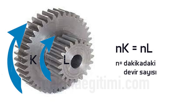
types of simple machines concentric gears

Concentric gears, since they are riveted to one another, always rotate in the same direction and have the same rotational speed.
Where n is rotational speed, nK = nL

See related topic: Types of Gears

Pulleys (Belt Pulleys)
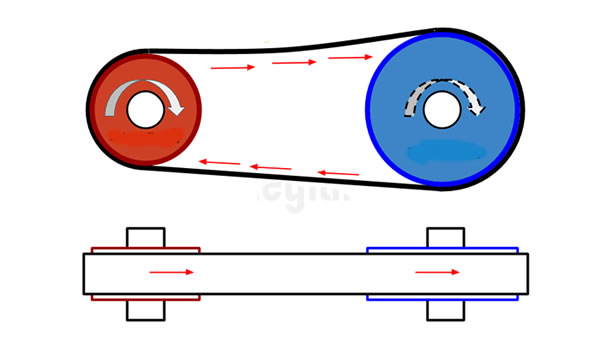
belt pulley straight connection
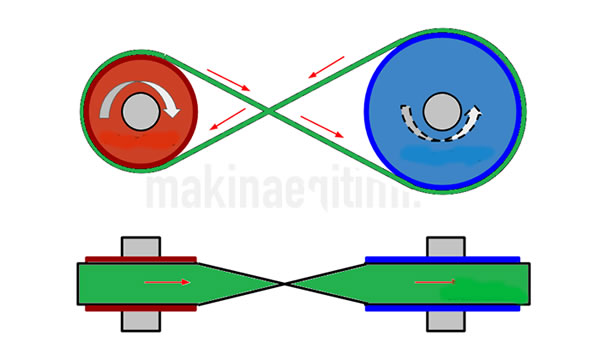
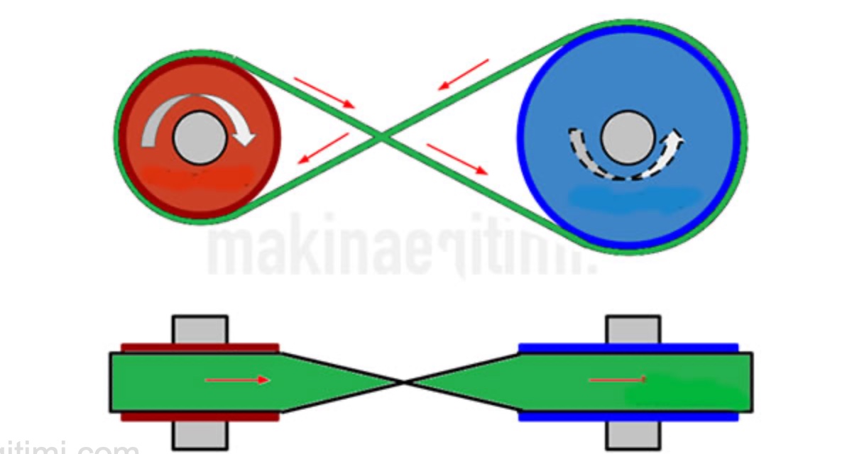
simple machines belt pulley crossed connection

Since pulleys have no teeth, they are connected to each other by a belt or a rope. They are generally used to transmit motion taken from a motor to another point. Their rotational speeds are also inversely proportional to their radii. Their direction of rotation, however, changes depending on how the belts are connected, as shown in the figure. In the picture on the left, both pulleys rotate in the same direction, while in the other picture, the two pulleys rotate in opposite directions to each other.

Related Questions

No, simple machines don’t provide any energy gain; they only make work easier to do by changing the direction or magnitude of the applied force. The total amount of work done actually stays the same.

Since energy stays constant, when work needs to be done with less force, the distance over which that force is applied must increase. In other words, a gain in force is balanced by a loss in distance; the two cannot be gained at the same time.

Related Posts

Pascal's principle science project examples, title image Science Fair Project Examples About Pascal Principle
Share. Facebook Twitter WhatsApp Tumblr Email Telegram Copy Link

Leave A Reply Cancel Reply


Engine Air Intake System and Components
Leonardo da Vinci’s Machines: The Flying, Fighting and Walking Inventions of a Renaissance Genius
  • Contact
  • Terms of Service
  • Privacy & Cookie Policy

Type above and press Enter to search. Press Esc to cancel.