
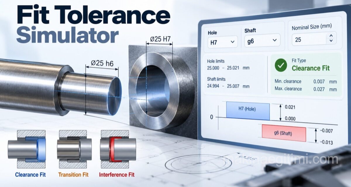
When a shaft goes into a hole, their relationship can turn out three different ways: the shaft rotates or slides freely (clearance fit), it’s fixed tightly in place (interference fit), or it could go either way depending on manufacturing tolerance (transition fit). What determines this relationship is the upper/lower deviation values of the shaft and hole. With the interactive simulator below, you can enter your own deviation values to instantly see the fit type, and watch the clearance or interference between the shaft and hole live in a cross-section view.
What Are Tolerance and Fit?
No part can be manufactured to the exact “nominal” size shown on a drawing — small deviations are inevitable due to the nature of manufacturing processes. That’s why a part’s dimension is defined between an acceptable UPPER LIMIT and LOWER LIMIT; the difference between these two limits is called tolerance. When two parts (say, a shaft and a hole) come together, the relationship between them is called a fit — the type of fit depends on where the shaft’s and hole’s tolerance limits sit relative to each other.

How Do You Read Deviation Values? (ES, EI, es, ei)
In standard tolerance notation, uppercase letters belong to the HOLE and lowercase letters to the SHAFT: ES (hole upper deviation) and EI (hole lower deviation), es (shaft upper deviation) and ei (shaft lower deviation).
These four values, in micrometers (µm), show how far a dimension may deviate from nominal, and are read from a standard tolerance table (ISO 286) or the fit table in your textbook. For example, with a 30 mm nominal diameter, ES=+25 µm, EI=0, the hole can be manufactured anywhere between 30.000 mm and 30.025 mm.
Fit Tolerance Simulator
Enter the nominal diameter and the hole/shaft deviation values (read from your standard tolerance table) into the tool below — the fit type, diameter ranges, and clearance/interference amount are calculated instantly. The clearance or interference shown in the cross-section is drawn at an exaggerated scale so the micron-level difference is visible to the eye.
The deviation values (ES/EI, es/ei) should be read from the standard tolerance table (ISO 286) or the fit table in your textbook. The tolerance class field (like H7/g6) is just a label; this tool does not auto-fill the micron values for a given letter/class — you must enter ES/EI/es/ei yourself from the table. The clearance/interference amount shown is not to real scale — it is exaggerated to be visible, and is meant only to show the type of fit and its relative size.
Frequently Asked Questions
These values are listed in ISO 286 standard tolerance tables, based on the nominal diameter range (e.g. 18-30 mm, 30-50 mm) and the chosen tolerance class (letter-number combinations like H7, g6, k6, p6). You can also read them from the fit table in your textbook or mechanical engineering handbook.
In practice, machining a hole (especially with standard drill/reamer sizes) is harder than machining a shaft’s outer diameter, so most production keeps the hole at a fixed reference class (usually H, meaning its lower deviation is 0) and achieves the desired fit type by only changing the shaft’s tolerance class — this is called the “hole-basis system.” Since this simulator lets you enter both sides’ deviations independently, you can calculate both hole-basis and shaft-basis systems.
Because both the hole and shaft can be manufactured to any size WITHIN their own tolerance range. In a transition fit these ranges overlap, so depending on the actual dimensions of a specific hole-shaft pair produced, the assembly can come out slightly loose or slightly tight — which is why it’s called “transition.”
Since the shaft is larger than the hole in an interference fit, pressing it in directly requires very high force and friction (and thus surface damage). Instead, the part with the hole is heated to expand it (or the shaft is cooled to shrink it), the temporarily clearance-fit assembly is joined easily, and once the parts return to room temperature they lock together tightly — this is called “shrink fitting.”
No. Real clearance/interference amounts are usually between a few micrometers and a few hundred micrometers (1 micrometer = 0.001 mm) — a difference far too small to see on a part drawn at millimeter scale. That’s why the clearance/interference shown is deliberately exaggerated, meant only to convey the TYPE of fit and its relative size.
Choosing the right fit type guarantees both that a machine part functions correctly and that it can be assembled/disassembled as needed. Use the simulator above to experiment with different deviation values and reinforce the logic of fits, and get a quick feel for the right tolerance class before diving into your own designs.
Related Posts
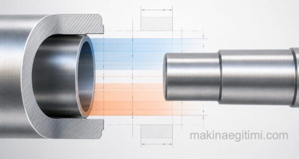 Fit Tolerances and Tolerance Pairs – Lesson 3
 Types of Sectioning in Technical Drawing? Sectioning Methods
 How Is Dimensioning Done? Rules of Dimensioning
 Geometric Dimensioning and Tolerancing
 Form and Position Tolerances in Technical Drawing
 Technical Drawing Instruments and Equipment
 Surface Roughness in Technical Drawing
 Geometric Drawings 3 – Drawing Polygons