Close Menu
  • MAKİNELER ve İMALAT
    • Tools & Equipment
    • Computer-Aided Drawing
    • CAD/CAM Education
    • CNC Machine Programming
    • Casting Technologies
    • Electrical & Electronics Technologies
    • Hydraulics & Pneumatics
    • Manufacturing Processes
    • Manufacturing Technologies
    • Occupational Safety
    • Mold & Die Design
    • Solid Modeling
    • Welding Technology
    • Machine Elements
    • Mechanical Trade Drawing
    • Materials Science
    • Automotive & Vehicle Technologies
    • Robotics Technologies
    • Health Technologies
    • Defense & Aerospace Technologies
    • Descriptive Geometry
    • Technical Drawing
    • Software & Hardware Technologies
    • Innovative Manufacturing Methods
  • TEKNOLOJİ ve YAŞAM
    • OTOMOBİLLER ve TAŞIT
      • Vehicle & Engine Knowledge
      • Safe Driving
      • Sürüş Destek Sistemleri
    • Genel Kültür
      • Movies & TV Shows
      • Görsel ve Grafik Sanat
      • Books & Literature
      • Music
      • Sports
      • History
      • History of Technology
    • GÜNDELİK YAŞAM TEKNOLOJİLERİ
    • Hobbies & Entertainment
    • Internet Technologies
    • Health
    • Mobile Technologies
Makine Eğitimi
  • Machines & Manufacturing
    Machine Elements
    Hydraulics & Pneumatics
    Technical Drawing
    Computer-Aided Design & Manufacturing
    Basic Manufacturing Processes
    Manufacturing Processes
    Industry Technologies
    Other Technical Courses
    Motion & Power Transmission
    Simple Machines
    Chains & Sprockets
    Shafts & Journals
    Gears
    Cams
    Couplings
    Belts & Pulleys
    Springs
    Bearings
    Keys
    Fastening Joining
    Retaining Rings
    Screws, Bolts & Nuts
    Cotter Pins
    Flanges
    Welding
    Rivets
    Pins & Bolts
    Washers
    Calculators
    Gear Ratio Calculator
    Spring Constant Calculator
    Belt Pulley Ratio Calculator
    Other Machine Elements
    Slides & Linear Guides
    Brakes
    Flywheels
    Clamps
    Shock Absorbers
    Gaskets & O-Rings
    Seals & Sealing Elements
    Hydraulics
    Introduction to Hydraulics & Principles
    Hydraulic Systems & Applications
    Accumulators
    Filters
    Motors
    Pumps
    Valves
    Pneumatics
    Introduction to Pneumatics & Principles
    Pneumatic Systems & Applications
    Pneumatic Circuit Components
    Valves
    Cylinders
    Silencers
    Motors
    Compressors
    Dryers
    Conditioning Units
    Common Topics & Maintenance
    Hydraulic & Pneumatic Maintenance
    Study Notes, Exams & Tests
    Technical Drawing
    Introduction to Technical Drawing
    Geometric Drawings
    Perspective & Projection
    Orthographic Views
    Dimensioning
    Sectioning
    Assembly & Detail Drawings
    Tolerances
    Surface Finish Symbols
    Mechanical Engineering Drawing
    Screws, Bolts & Nuts
    Pulley Drawings
    Gear Drawings
    Shafts & Journals
    Bearing Drawings
    Pins & Bolts
    Spring Drawings
    Welds in Technical Drawing
    Washers
    Cotter Pins
    Technical Drawing Exercises
    Mechanical Drawing Exercises
    Gear Exercises
    View Extraction Exercises
    Pulley Exercises
    Pin & Bolt Exercises
    Threaded Fastening Exercises
    Descriptive Geometry
    Computer-Aided Drawing
    AutoCAD Drawing Lessons
    Solid Modeling & Animation
    Solid Model Drawing Files
    Solid Model Assembly Examples
    Solid Model Drawing Lessons
    3D CAD Software Reviews
    Solid Modeling Exercises
    CNC Programming
    CAM
    Measurement & Inspection
    Dial Indicators
    Calipers
    Gauges
    Micrometers
    Materials Science
    Steels
    Cast Iron
    Aluminum
    Plastics
    Material Testing & Hardness Measurement
    Occupational Safety
    Workshop Safety
    Safety When Working With Electricity
    Machine Safety Rules
    Hand Operations
    Filing
    Marking
    Cutting Operations
    Reaming
    Tapping
    Threading With a Die
    Drill Bit Sharpening
    Working With Machines
    Basic Turning Operations
    Basic Milling Operations
    Shaper Machine
    Machining
    Turning
    Milling
    Grinding
    Innovative Manufacturing Methods
    EDM (Electrical Discharge Machining)
    Laser Machining
    Waterjet Machining
    3D Printing
    3D Scanners
    Welding
    Rolling
    Casting
    Mold & Die Design
    Mechanical & Hydraulic Presses
    Blanking & Piercing Dies
    Bending Dies
    Drawing Dies
    Plastic Injection Molds
    Extrusion Dies
    Compound Dies
    Progressive Dies
    Blow Molds
    Spinning Dies
    Spray Molds
    Manufacturing of Machine Parts
    Automotive & Vehicle Technologies
    Motor Vehicle Manufacturing
    Raw Material Production
    History of Technology
    Health & Medical Technologies
    Defense & Aerospace
    Robotics Technologies
    Software & Hardware Technologies
    Mechanics - Strength of Materials
    Physics Topics
  • Technology & Life
    Hobbies & Entertainment
    Sports
    Music
    Vehicle & Engine Knowledge
    Vehicle Maintenance & Repair
    Safe Driving
    Driver Assistance Systems
    History
    Movies & TV Shows
    Books & Literature
    Computers & Internet
    Computer Tips
    Software Reviews
    Hardware & Peripherals
    Practical & Safe Internet Use
    Visual & Graphic Art
    Mobile Technologies
    Travel
    Science
    Health
    First Aid Knowledge
    Everyday Technologies
Makine Eğitimi
Home»Machine Elements»Belt-Pulley Ratio Calculator
5 September 2026

Belt-Pulley Ratio Calculator

Belt-Pulley Ratio Calculator

Motors, compressors, machine tools, and countless industrial machines transmit motion between two pulleys connected by a belt. The pulleys’ diameter ratio determines how fast the output shaft turns and how much torque it produces. With the interactive calculator below, you can enter the diameters of two pulleys and the input speed to instantly calculate the belt ratio, output speed, belt speed, and optionally the output torque — and watch how two belt-driven pulleys actually turn with a live animation.

  • What Is a Belt-Pulley System?
  • How Is the Belt Ratio Calculated?
  • Belt-Pulley Ratio Calculator
  • The Difference Between a Belt-Pulley System and a Gear System
  • Applications of Belt-Pulley Systems
  • Frequently Asked Questions

What Is a Belt-Pulley System?

A belt-pulley system is a simple but widely used mechanical transmission method that transfers power from a driving pulley (usually connected to a motor shaft) to a driven pulley via a belt. Unlike gear systems, the pulleys don’t touch directly — the distance between them is bridged by the belt. This allows a specific distance to be kept between the two shafts, lets the belt partially absorb vibration and shock, and lets the belt slip under excessive load, protecting both the motor and the driven equipment.

How Is the Belt Ratio Calculated?

The belt ratio is calculated with the formula i = D2 / D1. Here, D1 is the diameter of the driving pulley (input, usually the motor side), and D2 is the diameter of the driven pulley (output). Once the ratio is known, the output speed is found with n2 = n1 / i, and the output torque with T2 = T1 × i — just like in gear systems, speed and torque are inversely proportional.

For example, if a 60 mm driving pulley turns a 180 mm pulley, the belt ratio is 180/60 = 3. If the input shaft turns at 1400 rpm, the output shaft turns at 1400/3 ≈ 467 rpm. Belt speed is calculated with v = π × D1 × n1 and is constant at every point of the belt — about 264 m/min in this example.

Belt-Pulley Ratio Calculator

Enter your own pulley diameters and input speed into the tool below to see the result instantly, and optionally add an input torque to calculate the output torque as well. You can also watch two belt-driven pulleys turning in the same direction with a live animation.

İnteraktif Hesaplama Aracı
Belt Ratio (i) —
Output Speed (n2) 0 rpm
Belt Speed (v) 0 m/min
Output Torque (T2) —

The belt ratio is calculated as i = D2/D1. If i > 1, speed drops and torque increases (reduction); if i < 1, speed increases and torque drops. Belt speed is constant at every point of the belt and slip is ignored. The rotation animation is not scaled to real speed — it only shows relative speed.


The Difference Between a Belt-Pulley System and a Gear System

Even though the formula structure is nearly identical, there’s an important difference between the two systems: meshed gears turn in OPPOSITE directions, while two pulleys connected by a belt (unless the belt is crossed) turn in the SAME direction, because the belt touches the same side of both pulleys in the same direction. Gear systems also run in perfect sync with no slip, while belt systems have a certain amount of slip — this makes belt systems more tolerant of overload but less suited to applications requiring precise synchronization.

Applications of Belt-Pulley Systems

  • Motor-compressor drives: reduce or increase the electric motor’s speed to what the compressor needs.
  • Lathes and drill presses: stepped pulleys offer multiple speed options.
  • Conveyor belt systems: convert motor speed to the speed the belt needs.
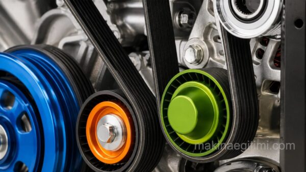
  • Automotive AC compressors and alternators: transfer power from the engine’s crankshaft at different speeds via a belt.

Frequently Asked Questions

Belt systems run quieter, allow a large distance between the two shafts, require no lubrication, and slip under excessive load to protect both the motor and equipment. Gear systems, on the other hand, are better suited to higher power transmission and more precise synchronization.

Belt speed affects the tension and wear the belt is subjected to. Most belt types have a maximum speed limit specified by the manufacturer; exceeding it shortens the belt’s life and increases the risk of failure.

This calculator assumes an ideal (slip-free) system. Real belt-pulley systems, especially flat belts, have a small amount of slip; V-belts and toothed (synchronous) belts largely reduce or completely eliminate slip.

The belt wraps around the outer surface of both pulleys from the same side, so it turns both in the same direction. If opposite rotation is desired, the belt can be mounted “crossed” — but this is rarely used in practice since it causes the belt to rub against itself.

In toothed (synchronous) belt systems, the pulley’s tooth count can be used instead of diameter; the formula stays the same, just ratio the driving and driven pulleys’ tooth counts (Z1/Z2) instead of D1/D2 — since with a fixed tooth pitch, tooth count is directly proportional to diameter.

Choosing the right pulley ratio is critical for both motor efficiency and the performance of the driven equipment. Use the calculator above to quickly get a feel for the right pulley pair before diving into your own projects.

Related Posts
What Is Riveting. How Is It Done? What Is Riveting. How Is It Done? gears slide presentation Bevel Gear Strength Calculations Bolt Types and Their Properties What Is a Bolt? Bolt Types and Their Properties Types of Belts Belt Types Used in Industry Compression Spring. Calculation and Drawing Compression Spring. Compression Spring Calculation and Drawing What Is a Timing Belt? What Does It Do? What Is a Timing Belt? What Does It Do? Kam Mekanizmalı Yaratıcı Otomatlar Creative Cam-Mechanism Automatons SolidWorks Assembly Example Differential Gears SolidWorks Assembly Example – Differential Gears
Belts & Pulleys
Share. Facebook Twitter WhatsApp Tumblr Email Telegram Copy Link

Leave A Reply Cancel Reply

The Fall of Constantinople: A City’s Downfall, an Era’s Dawn
How to Save Fuel in Vehicles
  • Contact
  • Terms of Service
  • Privacy & Cookie Policy

Type above and press Enter to search. Press Esc to cancel.