
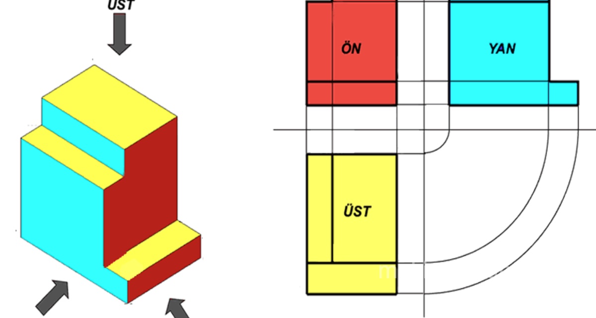
We covered projection planes and the epure in an earlier article. Let’s briefly touch on it again here;

There are 3 projection planes: the frontal, horizontal, and profile plane. This folded arrangement of these planes is called a dihedral angle (diedr).
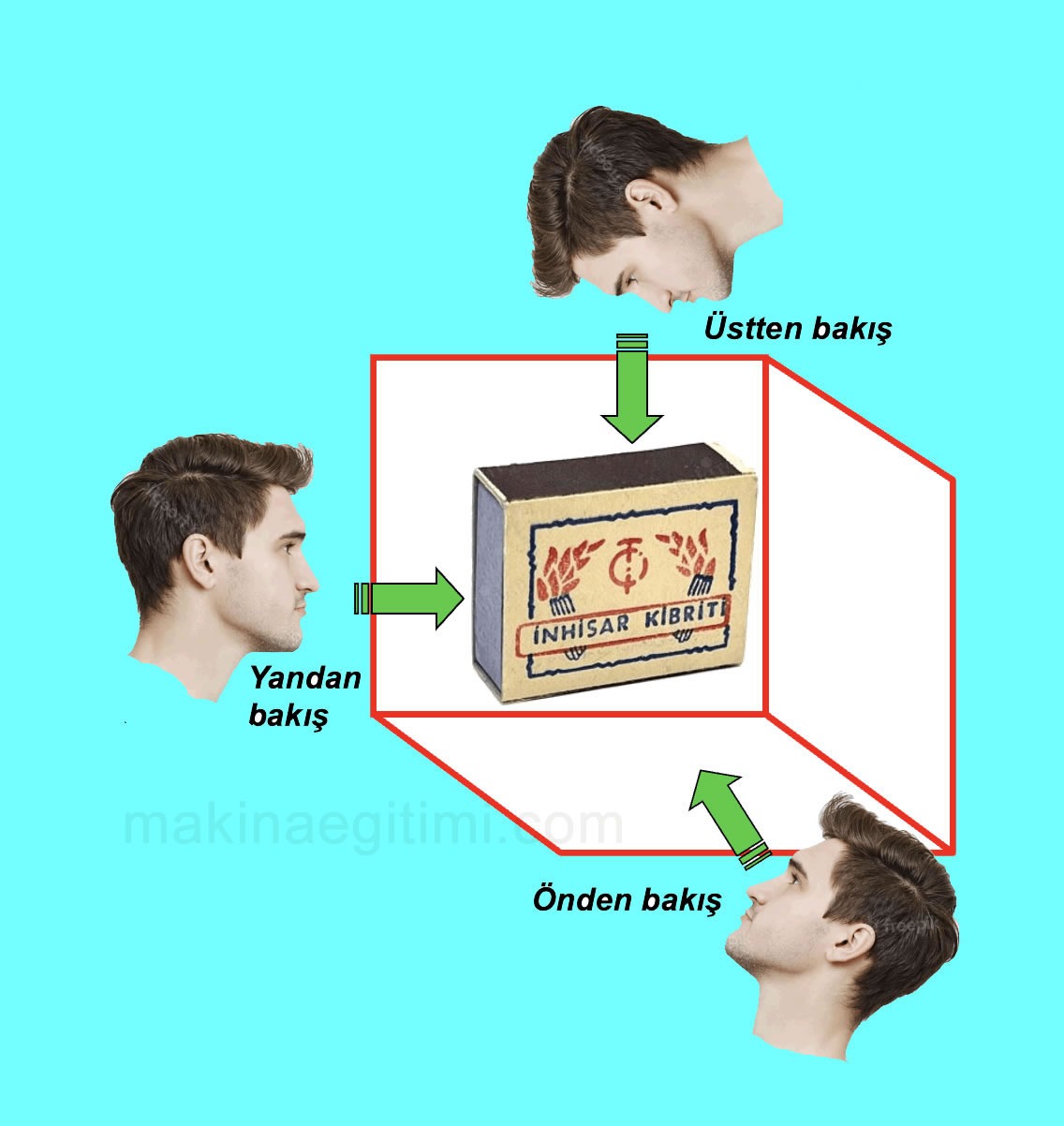
So that the manufacturer can get a full picture of all the details of the part, the technical drawing explains how the part looks when viewed from the top, front, and side.
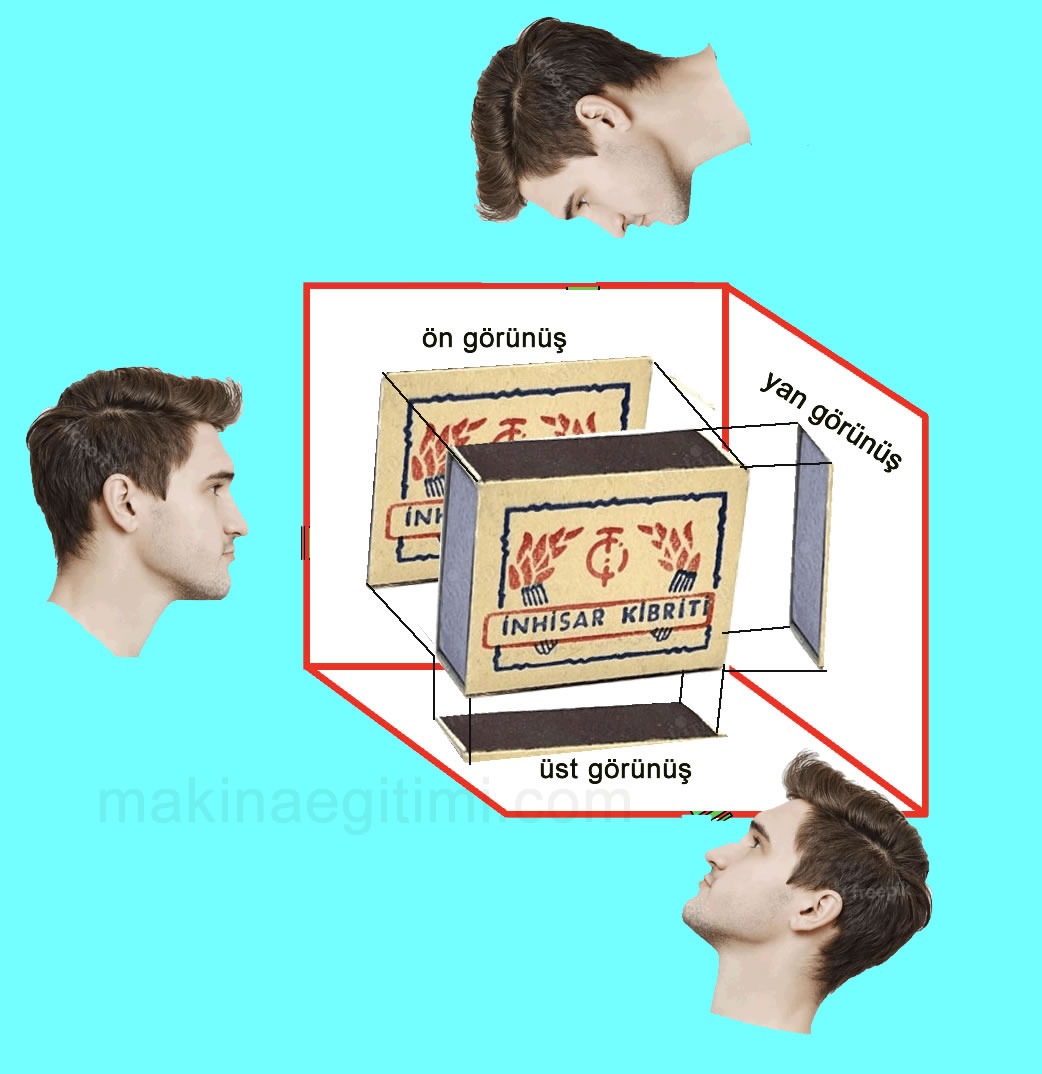
If the views of a 3D object — as seen from the front, top, and side — are projected onto the dihedral planes, it becomes easier to get a clear picture of the part.

In a technical drawing, the views of a part are drawn on the epure. The epure is the unfolded (opened-out) form of the dihedral angle.

In the figure above, we see the views of a matchbox on the epure plane.

In the figure above, to help you understand better, the faces of the 3D part are shown in yellow, red, and blue. The front, top, and side views have been drawn on the epure using these colors.
The Three-View Rule
In standard technical drawing, 3 views — front, top, and side — are usually enough to fully define a part.
Hidden Edge Lines
Edges that are behind the part and not directly visible are shown with dashed lines (hidden lines).
Use of Scale
Large parts can be drawn at a reduced scale like 1:2 or 1:5; small parts can be drawn at an enlarged scale like 2:1 or 5:1.
The Logic of Getting Views

Rays are sent from the object perpendicular to the horizontal, vertical, and profile planes, essentially casting the object’s shadow onto the planes.

In the next step, we’ll lift the object out from between the planes, leaving only its projections on the planes. (figure above)
Next, we’ll fold the horizontal plane downward and the profile plane to the right.
And here’s a simple 3-view drawing for you.

We can better understand how this folding process is done with the animated video above.
The purpose of projecting spatial shapes is to obtain the technical drawings of objects by converting the projections into an epure.

In the figure above, we see the process of finding a cube’s dihedral (left) and epure (right) projections.
Examples of Getting Views

Views of a triangular prism on the epure

Views of a rectangular-based pyramid on the epure
Related Questions
When the front, top, and side views are combined, all of the part’s basic dimensions — length, width, and height — become clear. For most parts, these three are enough to fully understand the shape.
These lines show the part’s edges that aren’t visible from the direction currently being viewed — edges that are behind or inside the part. This way, a hole or protrusion that can’t be seen from outside is still indicated in the drawing.
Related Posts
 How to Draw an Ellipse? Ellipse Construction.
 What Is Tolerance? Tolerances Lesson 1
 Geometric Drawings 2 – Dividing Circles
 Fit Tolerance Simulator
 Technical Drawing Instruments and Equipment
 Geometric Dimensioning and Tolerancing
 Introduction to Surface Finish Symbols
 Fit Tolerances and Tolerance Pairs – Lesson 3