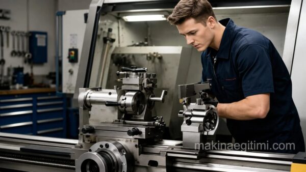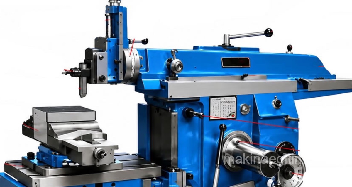
A machine tool that uses a reciprocating (back-and-forth) linear cutting tool (bit) to roughly machine flat surfaces is called a shaper (shaping machine).
It’s used for machining flat surfaces, profiled surfaces, internal and external grooves, and gear wheels. Although it once had an important place in manufacturing operations, it has now largely been replaced by multi-axis vertical machining centers, following advances in machine technology and especially cutting tool technology. It’s still used, however, in some small businesses and technical schools.
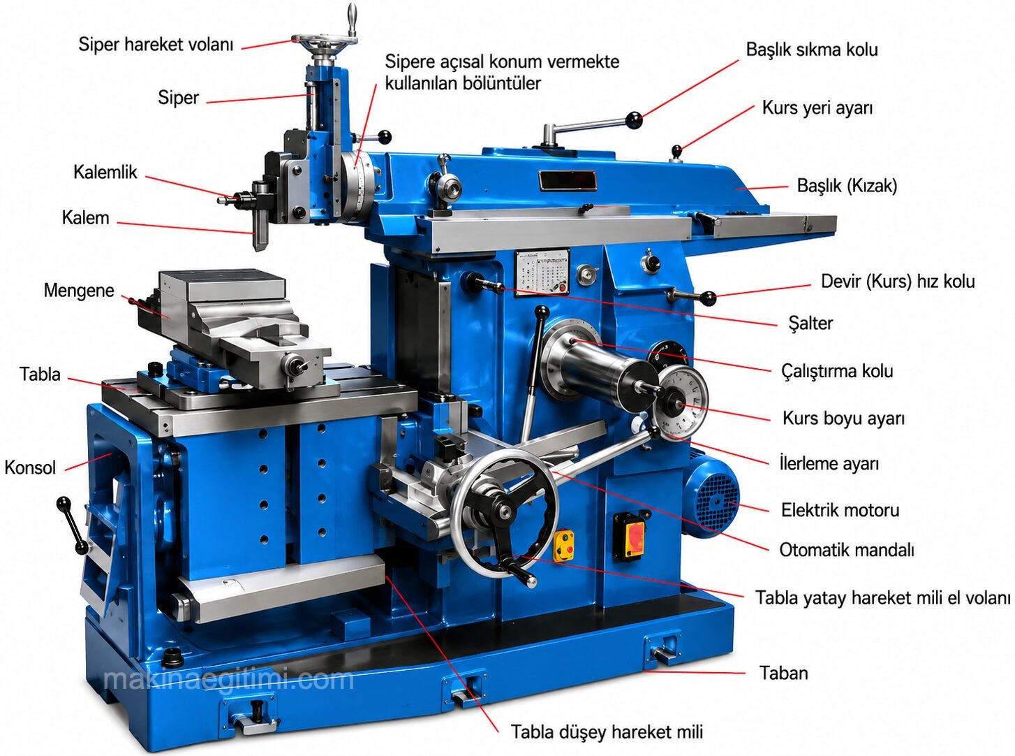
Parts of a Shaper
The parts of a shaper are shown in the figure below.
Types of Shapers:
1- Mechanical (crank-driven) shaper
2- Hydraulic shaper
Mechanical Shaper
In mechanical shapers, the rotational motion produced by the electric motor is converted into linear motion through various mechanical transmission components (an eccentric gear and a connecting rod), providing the cutting motion.
Working Principle of the Mechanical Shaper
The working principle of the shaper: the diagram below shows the mechanical drive system that gives the machine’s ram its linear-reciprocating (shaping) motion.
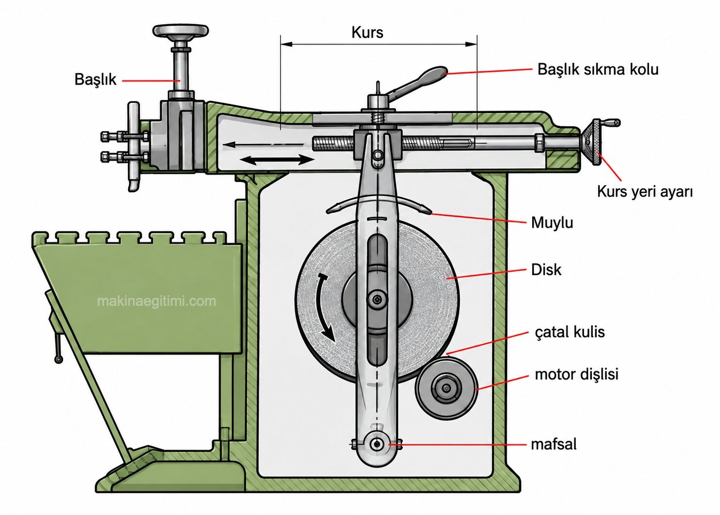
A small gear turned by the electric motor rotates the system’s large gear, i.e. the disc. As the disc rotates, the journal pin mounted on it rotates along with it. This journal pin is connected to the disc by a sliding block and fits inside the slotted link (rocker arm). This way, the rotational motion of the journal pin gives the slotted link an angular (oscillating) motion. The slotted link, which has a fixed pivot at its lower end and a sliding pivot at its upper end, is connected to the machine’s ram via a clamping bolt. Because of this, the angular (pendulum) motion of the slotted link is transferred to the machine’s ram as linear-reciprocating motion.
The stroke length is directly proportional to the orbit radius of the journal pin.
Hydraulic Shaper
Hydraulic shapers were the production machines on which hydraulic systems were first applied. Their systems are quite simple and basic. They have a simpler construction than mechanically operated shapers. As a result, they’re more efficient than mechanical shapers. On hydraulic shapers, speed can be set to any desired value.
A hydraulic shaper (shown in the figure below) operates using the power of pressurized fluid.
On this machine, the pump driven by the electric motor pushes hydraulic fluid (oil) through the directional valve into the cylinder. Pressurized oil advances the piston rod and the ram, operating the machine. The directional valve allows oil to enter the cylinder in two directions at set intervals, providing the forward-backward motion of the ram.
On a hydraulic shaper, the speed of the machine’s motion can be set to the desired value with a flow control valve placed in the fluid’s path. Hydraulic shapers are more powerful, cheaper, and easier to maintain and repair than mechanical shapers.
Advantages of the Hydraulic Shaper Over the Mechanical Shaper
1 — The system in a hydraulic shaper is very simple and basic.
2 — Noise and vibration are practically negligible, which allows for more precise work.
3 — The cutting speed can be set to any desired value.
4 — Maintenance, service, and repair of the hydraulic shaper are easier.
5 — Hydraulic shapers are cheaper.
6 — On a hydraulic shaper, the stroke length can be adjusted exactly to the desired dimension, making the machine more efficient.
7 — On a hydraulic shaper, the directional control valve can be controlled by electrical signals. This allows the machine to be remote-controlled, or to work together with programmable control systems, if desired.
8 — A hydraulic shaper has a longer service life, and the machine wears less over time.
9 — Provided a suitable hydraulic pump is used, the machine vise’s horizontal left-right motion and the cutter’s vertical up-down motion can be obtained from the same system, and the machine can even operate automatically if programmed.
10 — The cutting bit can be set to move slower on the forward (cutting) stroke and faster on the return stroke, and impact-free motion is achieved when the cutter changes direction.
As with any hydraulic system, the pressure drops caused by the function of the hydraulic circuit’s components also somewhat reduce the shaper’s efficiency. Leaks occurring at pipes and fittings can also cause pressure drops.
To keep pressure drops to a minimum, suitable pipes and fittings, sealing elements, and hydraulic oil appropriate for the system should be used. In addition, at low temperatures, the increased viscosity of hydraulic oil makes it harder to flow. This causes a drop in the machine’s efficiency. For this reason, when starting work on a shaper in cold temperatures, the machine is run idle for a short period first. This allows the hydraulic oil to circulate through the system once or twice and warm up.
Forward-Cut, Return-Idle Principle
A shaper cuts during the ram’s forward stroke and moves idle during the return stroke.
Crank Mechanism
The shaper’s ram motion is provided by a crank mechanism that converts rotational motion into linear motion.
Flat Surface and Slot Machining
Shapers are especially used for machining flat surfaces and keyways.
Related Questions
Modern multi-axis machines can do the shaper’s work much more efficiently, offering faster and more versatile machining. This technological progress has confined the shaper mostly to small workshops and educational use.
The rotational motion produced by the electric motor is converted into reciprocating (back-and-forth) motion through mechanical transmission components such as an eccentric gear and a connecting rod. This conversion makes the cutting bit move back and forth in a straight line.
Related Posts