

Surface Roughness
In machine construction, how surfaces that work together relate to each other is very important in terms of the job they perform. The precision of surfaces that rub against each other affects the machine’s efficiency while it operates.
Machine parts with uneven surfaces run noisily wherever they operate and wear out quickly. Precisely machined parts suited to their purpose, on the other hand, work together smoothly and increase the machine’s efficiency.
The shape and undulations that occur on a manufactured part’s surface are called roughness. The roughness value is measured on the part, in μm, using a device called a profilometer. The shape and undulations on the surface of a part are shown below.

Surface Roughness Values and Grades
Surface roughness values have traditionally been shown on technical drawings with various symbols. In today’s drawings, the use of the Ra (average surface roughness, roughness average) standard is commonly accepted. The table below also gives the equivalent values of other standards corresponding to Ra values.

Not all surfaces of a part may have the same properties after manufacturing. To avoid increasing cost, surfaces should be only as smooth and free of roughness as required. To prevent inconsistencies in practice, surface qualities have been standardized and are explained in ISO 1302/1992 and TS2040/February 1999.
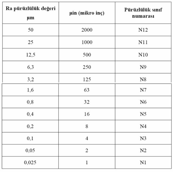
According to these standards, 12 surface quality grades have been defined. The roughness grade numbers corresponding to Ra arithmetic mean roughness values are given in the table above.
Table of Surface Roughness Values by Machining Method

Surface Roughness Values of Various Machine Parts (Ra = µm)
Based on information gathered from the practices of various factories, the surface roughness values used on some machine elements are given in the table below in Ra µm.


Surface roughness values for selected working surfaces of various machine parts. Examples such as: the outer surface of a cast part. Bearings. The inner surface of a gear. The inner surface of a flange, the outer surface of a pulley. (Below)


How Surface Roughness Is Shown

Roughness Symbol
Surface roughness in a technical drawing is shown with a standard “check mark” symbol.
Difference Between Ra and Rz
Ra represents the average roughness, while Rz shows the difference between the highest peak and the deepest valley.
Relationship to Machining Cost
Requesting a lower (smoother) surface roughness generally increases machining time and cost.
Related Questions
When rough surfaces rub against each other, irregular contact points form, which causes vibration and noise. Smoothly machined surfaces slide against each other more consistently, allowing quiet, efficient operation.
Making every surface extremely smooth unnecessarily increases machining time and cost. For this reason, only the surfaces that functionally require precision are machined to a high quality, while others can be left rougher as needed.
Related Posts
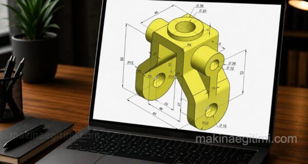 Dimensioned Isometric Drawing Examples – Part 3
  Technical Drawing Paper Sizes and Folding
  Types of Sectioning in Technical Drawing? Sectioning Methods
  What Is Projection? Projection Methods
 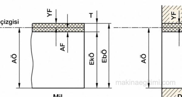 Tolerance Terms and Their Meanings in Mechanical Engineering
  How to Draw an Ellipse? Ellipse Construction.
  Geometric Drawings 2 – Dividing Circles
  Technical Drawing Instruments and Equipment