

In this article, in our Technical Drawing lessons section, we’ll cover how dimensioning is done. What to watch for when dimensioning. What is size and location dimensioning? What are the basic rules of dimensioning. We’ll also cover common dimensioning mistakes.
When dimensioning a drawing, a draftsman should picture in their mind the order of operations the part will be manufactured in, the manufacturing methods, and the finished part’s function on the machine, and only then dimension the drawing. Dimensions should be shown on the drawing in such a way that the worker never has to do calculations or measure the drawing.
Dimensioning Elements
Dimensions are shown on drawings using four drawing elements. These are shown in the figure below.
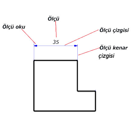
Extension line
These extend slightly past the arrowheads. The amount they extend varies based on the size of the arrowhead and dimension line.
Dimension line
These are continuous thin lines with arrowheads at their ends, indicating the size and location of the shape elements that make up the parts.
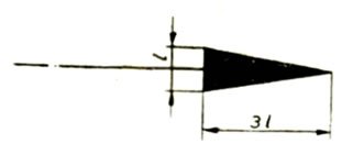
Arrowheads
There’s a 1-to-3 ratio between the edges that form the arrowhead. Their length varies between 3-5 mm depending on the size of the dimension line.
Dimension figure
These are written above and slightly clear of the middle of the dimension line. Dimension figures are all the same height, generally made 2.5 or 3 mm tall.
What Are Size and Location Dimensioning?
Size Dimensioning
Dimensioning the geometric shapes on a machine part is called size dimensioning. (example below)
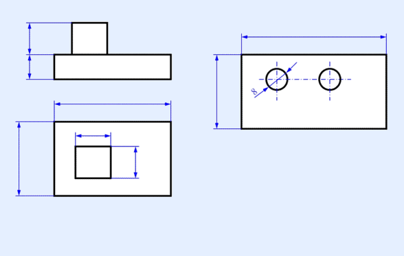
In this example we’re giving the manufacturer the part’s dimensions. We’re giving the diameter of the drill bit to be used to drill the hole. But there’s still missing information — for example, where will the hole be? How far apart will the two holes be?
Location Dimensioning
Dimensioning the positions of the geometric shapes on a machine part, relative to the part, is called location dimensioning. (example below)

The manufacturer needs to know how far away the hole is, and in which direction, on the part above. If we don’t provide this information, problems will arise.
How to Do Size and Location Dimensioning

Whether it’s size dimensioning or location dimensioning, a neat, organized-looking dimensioning like the one below is preferred over a scattered-looking one like the one above. Pay attention to the differences between the two dimensioning styles.

Actually, we can say that dimensioning in technical drawing is “using size and location dimensioning together in a way that doesn’t violate dimensioning techniques, doesn’t confuse the person reading the drawing, and isn’t contrary to manufacturing techniques.”
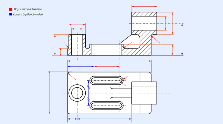
A production drawing includes both size and location dimensioning. (figure above) Neglecting either of these will create problems during manufacturing. Imagine a machinist who knows where to drill a hole but doesn’t know the hole’s diameter.

Note: Location dimensions should be given in the top view, where cylinders show up best. (example above)
How to Do Chain and Parallel (Baseline) Location Dimensioning
Giving location dimensions in a chain, for a number of identical shapes lying in the same direction and on a common axis, is called CHAIN DIMENSIONING.

Dimensioning like the example above can be used in cases where the cumulative error in location dimensions doesn’t cause a problem for how the part is used.
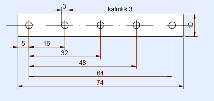
Another dimensioning style for the same part. (figure above) This type of dimensioning is used in cases where the cumulative error possible in chain dimensions given along the same direction would be a problem for how the parts are used.
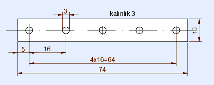
If dimensions repeat each other, instead of dimensioning them one by one, they can also be dimensioned as repeat count x dimension, as shown above.

Arrowheads are normally placed between the extension lines of a dimension, but can be placed outside if there isn’t room. In chain-dimensioned drawings, where there’s no room for an arrowhead due to lack of space, filled-in common points (dots) can be used instead of two opposing arrowheads. (above)
How to Do Parallel (Baseline) Location Dimensioning
In some cases, location dimensions need to be given relative to a specific reference point. In these cases, parallel (baseline) dimensioning is preferred.

Above, two different dimensioning styles for the same part are given. Except when unavoidable, dimension lines shouldn’t cross each other. This rule was ignored in the image on the left. Also, there’s something visually unpleasant about how part 2 is dimensioned on the left.
Basic Rules of Dimensioning
Dimensions shouldn’t be written repeatedly in various views, or repeated in different ways. Dimensions not needed for manufacturing the part shouldn’t be included.

Dimensions should be placed between the surfaces or axes that will make inspection and marking easier, keeping in mind where the part will be installed and its manufacturing method. For example, for the part above, the distance between the axes matters because we need to know the drill’s feed distance.

Dimensions should be given in such a way that, during manufacturing, the worker never has to calculate or measure the drawing to find a given dimension. (In the example above, in the first drawing the worker has to calculate the part’s overall length.)
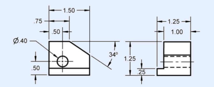
Dimensions should be given in the views that best show the shape of the part. Dimensions shouldn’t be given from hidden edges unless unavoidable. Dimensions should be given on views showing the true size. (For example, it would be a mistake if the 40 mm diameter hole in the image above had been dimensioned on the side view, where it appears with hidden lines.)

To prevent arrowheads and extension lines from crossing each other, overall dimensions should be placed on the outside, and smaller dimensions toward the inside. (above)
Extension lines shouldn’t connect two views; a given dimension should only belong to a single view.
Object lines shouldn’t be used as dimension lines.

Care should be taken not to give dimensions from unmachined surfaces.As with the 15 and 45 dimensions given in the image above, if dimensions need to be given relative to a machined surface, or from a rough surface, they should be given from the centerlines/axes instead.
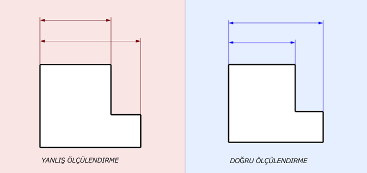
Dimension lines should cross each other as little as possible.(above)

A centerline, extended, can serve as an extension line. (above)
Centerlines shouldn’t connect two views.
Dimension figures should be written to be read from the bottom and right side of the sheet.

Unless unavoidable, dimension lines shouldn’t cross hatched surfaces, and dimensions shouldn’t be placed there. If they must be, the hatching lines where the figure is written should be erased.
Notes should always be written horizontally relative to the sheet, and should be short and to the point.
Radius dimensions of arcs whose center isn’t defined should have the radius symbol R placed in front of them.
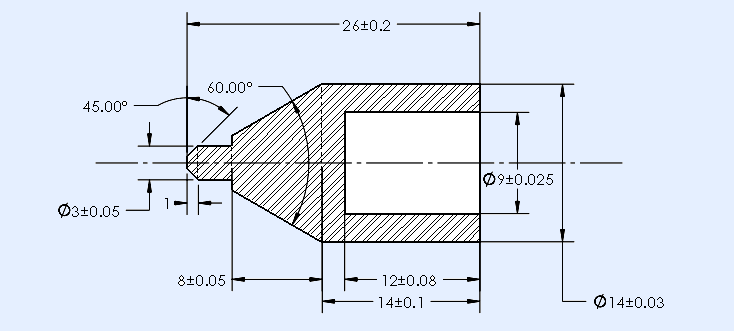
The angle or taper needed by the lathe operator should be indicated on tapered surfaces. (the part shown as 60º above)
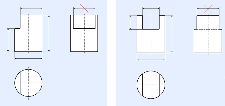
Dimensions shouldn’t be given for surfaces that naturally result from the manufacturing process. (the dimensions marked with X in the example above)
In this article we’ve given an illustrated explanation for those wondering how dimensioning is done, and provided general information about the dimensioning process. In our next articles, we’ll cover detailed dimensioning techniques and dimensioning rules in more depth. (Diameter, radius, and chamfer dimensioning, dimensioning tapers, etc.) We hope this was helpful.
Related Posts
 Choosing Tolerance Zones and Fits
  Geometric Drawings 2 – Dividing Circles
  Form and Position Tolerances in Technical Drawing
  What Is Tolerance? Tolerances Lesson 1
  Technical Drawing Paper Sizes and Folding
  How to Draw an Ellipse? Ellipse Construction.
  Specifying the Manufacturing Method by Surface Roughness
  Technical Drawing View Extraction Examples 1