
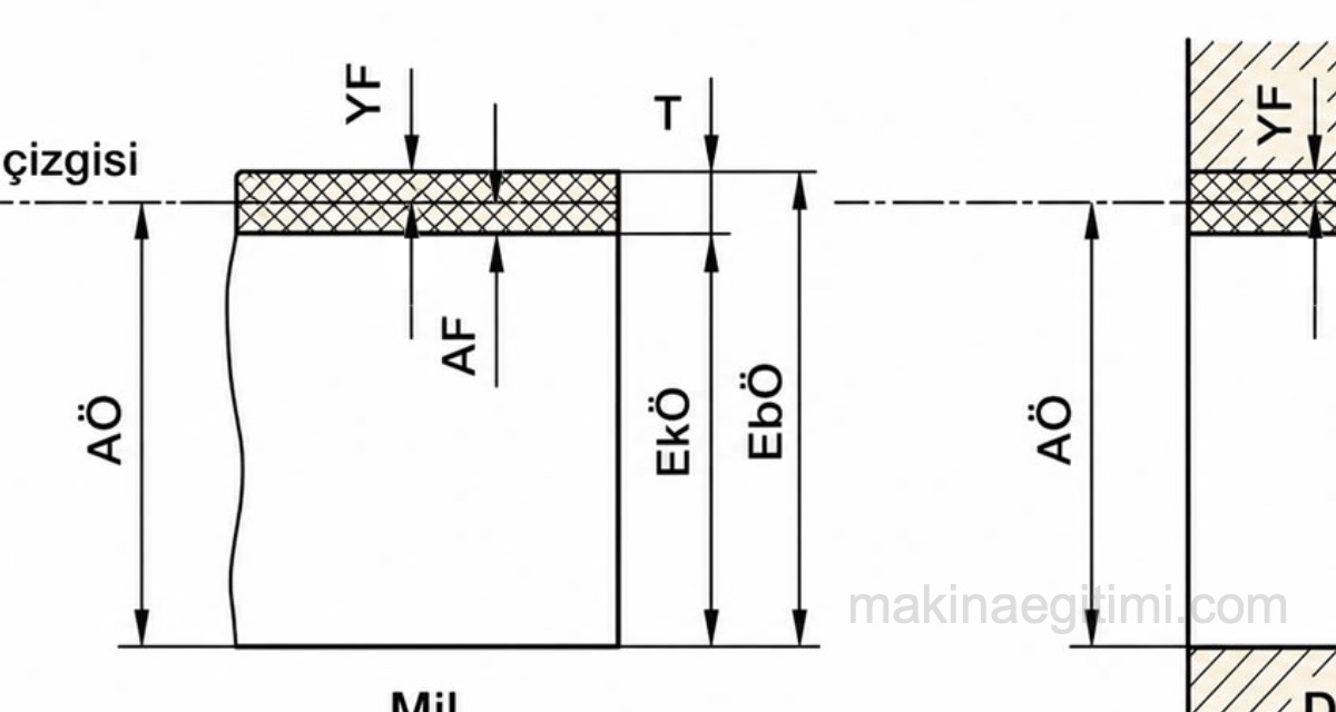
Tolerance terms: For the part to be manufactured to suit its purpose, it’s enough for it to fall between two acceptable limit values. The difference between these two dimensional values is called the tolerance. Every part is given a basic (nominal) size, and each of the two limit values is expressed as a deviation from this basic size — in the tolerance tables you’ll see later, these deviation values are given by diameter group.
The figure alongside shows the tolerances and deviations on a shaft and a hole (the male and female parts). In the figure, both deviations of the shaft are negative, while the hole’s deviations are positive. In other words, this is a clearance fit.
The following symbols are used:
Upper deviation of the hole: ES,
Lower deviation of the hole: EI,
Upper deviation of the shaft: es,
Lower deviation of the shaft: ei

Let’s go through the tolerance terms shown in the figure, which are frequently used in tolerance topics, one by one.
Size: A number expressing the numerical value of a length in the chosen unit. When written on a drawing, it’s called a dimension.
Actual Size of a Part: The actual size of a part is the size obtained in practice; it can be found by measurement.
Limit Sizes: The two acceptable extreme sizes of a part. The actual size must fall within the range covered by these two limit sizes.
–Maximum Size: the larger of the two limit sizes.
– Minimum Size: the smaller of the two limit sizes.
–Basic (Nominal) Size: the size taken as the reference for defining the limit sizes.
Deviation: The algebraic difference between a size (actual size, maximum size, etc.) and the corresponding basic size.
Actual Deviation: The algebraic difference between the actual size and the corresponding basic size.
Upper Deviation (ES, es): The algebraic difference between the maximum size and the corresponding basic size.
Lower Deviation (EI, ei): The algebraic difference between the minimum size and the corresponding basic size.
Zero Line: In the graphical representation of tolerances and fits, this is the straight reference line for deviations. It’s also the line with zero deviation, corresponding to the basic size. Positive deviations are shown above this line, negative deviations below it.
Tolerance: The difference between the maximum size and the minimum size. In other words, the algebraic difference between the upper deviation and the lower deviation. Tolerance is an absolute value with no sign.
Tolerance Unit: In a system, this is the factor forming the basis for defining the fundamental tolerances, expressed only as a function of the basic size (each tolerance equals the tolerance-unit value corresponding to its basic size, multiplied by a coefficient specific to each tolerance grade).
Basic Shaft and Basic Hole Systems
Basic Shaft: In this system, this is the shaft whose upper deviation is zero; more generally, it’s the shaft chosen as the base in a basic-shaft system of fits.
Basic Hole: In this system, this is the hole whose lower deviation is zero; more generally, it’s the hole chosen as the base in a basic-hole system of fits.

Go Limit: Of the two limit sizes, the one corresponding to the maximum amount of material. This size is the upper limit size for a shaft, and the lower limit size for a hole.
Basic Shaft System
In the basic shaft system, the shaft diameter is kept fixed and different types of fit are obtained by varying the hole tolerance.
Basic Hole System
In the basic hole system, the hole diameter is kept fixed and different types of fit are achieved by varying the shaft tolerance.
Industrial Preference
Because it’s easier to manufacture, the basic hole system is used more widely in industry than the basic shaft system.
Fits
Fit: The relationship resulting from the difference in size, before assembly, between two parts that are to be joined together.
Basic Size of a Fit: The common basic size value of the fit’s two members.
Fit Tolerance: The arithmetic sum of the tolerances of a fit’s two members.
Clearance: The positive difference between the hole and shaft sizes before assembly.
Interference: The absolute value of the negative difference between the hole and shaft sizes before assembly.
Clearance Fit: A fit that always results in clearance. In other words, a fit in which the hole’s tolerance zone lies entirely above the shaft’s.
Transition Fit: A fit that can produce either clearance or interference. The tolerance zones of the hole and shaft overlap.
Clearances and Interferences
Minimum Clearance: In a clearance fit, the difference between the minimum size of the hole and the maximum size of the shaft.
Maximum Clearance: In a clearance or transition fit, the difference between the maximum size of the hole and the minimum size of the shaft.
Minimum Interference: In an interference fit, before the parts are assembled, the absolute value of the (negative) difference between the maximum size of the hole and the minimum size of the shaft.
Maximum Interference: In an interference or transition fit, before the parts are assembled, the absolute value of the (negative) difference between the minimum size of the hole and the maximum size of the shaft.
System of Tolerances: A standardized system of tolerances and deviations.
System of Fits: A system of fits between shafts and holes within a system of tolerances.
Basic Shaft System of Fits: A system of fits formed by combining various holes with a single shaft (or, keeping the same fundamental deviation, with shafts of different tolerance grades as needed) to obtain different clearances and interferences. In this system, the basic shaft is the shaft whose upper deviation is zero.
Basic Hole System of Fits: A system of fits formed by combining various shafts with a single hole (or, keeping the same fundamental deviation, with holes of different tolerance grades as needed) to obtain different clearances and interferences. In this system, the basic hole is the hole whose lower deviation is zero.
Related Questions
No manufacturing method can reproduce the exact same size, millimeter for millimeter, every single time. By defining an acceptable deviation range that won’t compromise the part’s function, tolerance makes production both possible and economical.
This describes a situation where the shaft’s deviations are negative — meaning the shaft is always slightly smaller than its basic size. This small difference creates a clearance that lets the two parts fit together easily, without binding.
Related Posts
 Fit Tolerances and Tolerance Pairs – Lesson 3
  What Is Projection? Projection Methods
  What Is Perspective. Types of Perspective and Exercises
  Dimensioned Isometric Drawing Examples – Part 1
  What Is Tolerance? Tolerances Lesson 1
  Form and Position Tolerances in Technical Drawing
  Types of Technical Drawing Paper
  Geometric Drawings 2 – Dividing Circles