
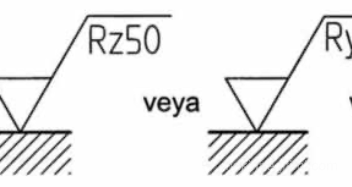

Surfaces that will receive special treatment are indicated with a thick chain (dash-dot) line. The type of treatment, such as chrome plating, painting, etc., is indicated on it along with its dimensions.

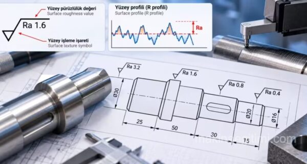
Surface roughness values for gear wheel surfaces are placed on the gear’s mean diameter (Dm). (figure-b above)
If the tooth surfaces of gear wheels are to be hardened or receive an additional treatment, similarly, “hardened,” “ground,” etc. is written. The hardness level is written as HRc (Hardened Rockwell hardness). (figure-c above)
Since the mating surfaces of assembly parts must be machined to the same surface quality, they’re indicated as shown below.

If a drawing has angular or arc dimensions, the surface roughness values can be placed on the angle lines or the arc dimension line. (figure-a below)

Surface roughness symbol marks that don’t fit on the part can be placed by extending them out onto the dimension leader line. (figure-b above)
Use of Standard Symbols
In technical drawing, specially treated surfaces are indicated with special symbols in accordance with the ISO standard.
Specifying the Coating
Special surface treatments such as chrome plating or hardening must also be indicated on the drawing with a note.
Relationship with Tolerance
Specially treated surfaces are generally specified together with tighter dimensional tolerances.
Related Questions
This special line type clearly tells the manufacturer or worker that this surface will receive an additional treatment, such as chrome plating or hardening, beyond standard machining. A special notation is used so it isn’t confused with standard lines.
When two surfaces with different roughness rub against each other, the rougher side quickly wears down the other. The same surface quality allows the two parts to work together in a balanced way with a long service life.
Related Posts
 Technical Drawing Instruments and Equipment
 What Does a T-Square Do, How Is It Used?
 Geometric Drawings 3 – Drawing Polygons
 Surface Roughness in Technical Drawing
 Hatching Lines in Technical Drawing
 Dimensioned Isometric Drawing Examples – Part 2
 Geometric Drawings 1 – Dividing Lines and Erecting Perpendiculars
 Dimensioned Isometric Drawing Examples – Part 3