
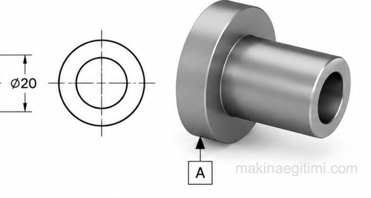
In technical drawing courses, we’ll discuss what are known as geometric tolerances: form and position tolerances, profile tolerances, and runout tolerances. We’ll cover how they’re shown in technical drawings and what the symbols mean.
Take a part designed like this:

What happens if it’s manufactured like this?

The part’s tolerance was given as ±0.3 mm. When we measure the part, we get 50.3 and might think it was machined within tolerance. But when we measure at the middle, we get 50.1.
Depending on where it’s used, for a part to be acceptable it may need to be not just dimensionally correct, but also straight, round, cylindrical, flat, etc.
Geometric Tolerancing
The need to tolerance not just the size of part features but also their other properties gave rise to a more precise tolerancing method called geometric tolerancing.
This new approach let designers tolerance form, orientation, location, runout, and profile values, as given in the table below, whenever needed.
This kind of tolerancing paved the way for the highest possible level of interchangeability.
We can group geometric tolerancing into 3 main categories:
Purposes of geometric tolerancing
Reduce manufacturing costs.
Ensure the true function and relationships of part features are considered during design.
Establish a common language between design, manufacturing, and inspection.
Understand/keep up with advanced technology.
Advantages of geometric tolerancing
Cost reduction

Which of these two example parts do you think is more expensive to manufacture?
In the first part, was the tolerance given for the part’s thickness meant to ensure the parallelism of the part’s two surfaces, or is the thickness dimension itself really critical?
If the part’s thickness isn’t critical (if the part has no fit relationship with another part), it’s more sensible to give a wide tolerance on that dimension and control parallelism with a geometric tolerance instead. The second part was designed with exactly this idea in mind.
The second part will be manufactured at a lower cost than the first.
Making sure the true function and relationships of part features are considered during design

The dimensioning above shows that for the hole’s position, datum A has first priority and datum B has second priority. The designer is saying that it’s important, for the function of the assembly, that the A surfaces of the two parts rest against each other.
The operator machining this part will rest the part on surface A, locate it against surface B, and then drill the hole.
Likewise, the inspector measuring the part will rest it on surface A, locate it against surface B, and then take the measurement.
Creating a common, easy-to-learn language

THE THREE HOLES WILL BE WITHIN THE CORRECT POSITION, WITHIN A TOLERANCE OF Ø0.25 AT MAXIMUM MATERIAL CONDITION, RELATIVE TO DATUMS A, B, C.
SURFACE B WILL BE PERPENDICULAR TO SURFACE A WITHIN 0.03.
SURFACE C WILL BE PERPENDICULAR TO SURFACES A AND B WITHIN 0.03
Datum Selection
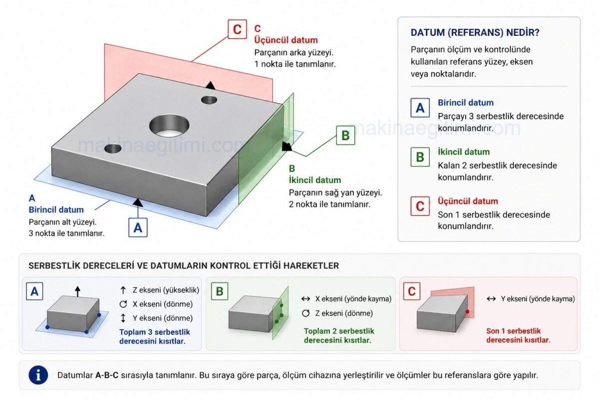
A datum is the feature on a part needed so that dimensioning related to the part can start from the correct place. Datums are usually chosen from features that are physically accessible and have a functional relationship with the feature being toleranced. In workshops, the surface of measuring plates, machine beds, or the locating surfaces of fixtures are used as datums.
Datums don’t always have to be “visible.” Invisible surfaces, axes, lines, or points that can be calculated using other features can also be used as datums.
For example, when we say a mountain is 1600 m tall, sea level is accepted as the datum. Here, a theoretical datum is being established to define the mountain’s height. In manufacturing too, bolt pitch diameters and features created through software are used as invisible datums. It should be recognized, though, that reaching and using this kind of datum is more difficult.
Datums are taken into account while parts are being designed, manufactured, and measured. The datums a designer specifies must also be traceable and accessible to the manufacturer and the inspector.
Applying the Datum Symbol
When a feature of a part needs to be defined as a datum, the datum is shown with a capital letter and connected to the feature with a triangle. The connecting triangle can be filled or open. (Figures 1 and 2 below)

The datum triangle is placed either directly on an outline of the feature, or on an extension line drawn from the outline (Figure 3 above)
When the datum is an axis or a mid-plane, the datum triangle is placed on the dimension line (Figures 4, 5, and 6 below).

If there isn’t enough room for two arrowheads, the datum triangle can take the place of one of the arrows (Figures 5 and 6 above).
If the datum triangle is placed directly on the axis, it must be clearly shown which feature is the datum. (Figure 7)

If a surface has been chosen as the datum, the datum triangle is placed on a line extending from a point on that surface (Figure 8).
If the geometric tolerance frame can be connected directly to the datum, a letter for the datum may not be needed. (Figure 9)
What the Symbols in Geometric Tolerances Mean

Form Tolerances (Not Related to a Datum)

These tolerances are given without reference to any datum. When setting the tolerance values, the value of the size tolerance must be taken into account.
The value of the geometric tolerance must be less than half the value of the size tolerance. When the toleranced feature is at its maximum material condition, its surface (or surfaces) must not extend beyond the envelope that defines the perfect dimensional form (the envelope rule).
Profile Tolerances (Related or Not Related to a Datum)

Profile tolerances relate to the profile of a line or a surface. These tolerances can be given with reference to a datum. They define how far a geometrically defined line or surface is allowed to deviate from the defined profile.
Orientation Tolerances (Related Feature)

Perpendicularity, parallelism, and angularity are tolerances related to the orientation of a feature. These tolerances are given with reference to a datum. When specifying these tolerances, the material condition (MMC or LMC) must be stated. Keep in mind that perpendicularity, parallelism, and angularity tolerances also control flatness and straightness.
Location Tolerances (Related Feature)

Symmetry, position, and concentricity are tolerances related to the location of a feature. These tolerances are given with reference to a datum. When specifying position tolerance, the material condition (MMC or LMC) must be stated. Symmetry and concentricity apply only under RFS and MMC/LMC do not apply to them.
Keep in mind that symmetry tolerance also controls flatness and straightness, position tolerance also controls straightness and perpendicularity, and concentricity tolerance also controls flatness and straightness.
Runout Tolerances (Related Feature)

Runout tolerances relate to the position of a cylindrical feature’s surface of revolution relative to its axis, or to the wobble of face surfaces. These tolerances are given with reference to a datum.
Keep in mind that circular runout tolerance also controls circularity and concentricity, and total runout tolerance also controls straightness, angularity, taper, circularity, and flatness on the face.
Related Posts
 Dimensioned Isometric Drawing Examples – Part 3
 Hole and Shaft Tolerances
 Technical Drawing View Extraction Examples 2
 How to Do Sectioning in Technical Drawing
 Fit Tolerances and Tolerance Pairs – Lesson 3
 Showing Specially Treated Surfaces in a Drawing
 How to Draw an Ellipse? Ellipse Construction.
 How Is Getting Views Done