

Drawing and dimensioning the views for manufacturing a machine part is not enough on its own. That only identifies the part by its dimensions and shape. For the part to work correctly and perform its function, its surfaces need to be machined properly.
It must be stated on the drawing, using symbols, marks, and words, which machine the part will be made on and what quality the surfaces need to be. Otherwise, after manufacturing, the parts will not work together properly and will not have a long service life. Yet what people expect from advancing technology is machines that are highly efficient, quiet, and long-lasting.
For these reasons, surface finish symbols must be placed on manufacturing drawings according to the part’s operating conditions. These symbols are applied to drawings according to the TS 2040 (February 1999) standard.
Symbols Used in Surface Finish Symbols
Surface qualities are indicated on manufacturing drawings with various symbols. This determines the production method, the machine to be used, and any additional processing.

a) Basic Symbol: the symbol for “a surface that is addressed/processed”
b) Symbol for a Surface Where Material Is Removed
c) Symbol for a Surface Where No Material Is Removed
NOTE: None of these three symbols gives any information about the surface roughness
Symbol Used for Special Cases
When special surface condition information must be shown, a horizontal line should be added to the long leg of the relevant graphic symbol. On this horizontal line, the special processes to be applied to the surface (reaming, scraping, hardening, etc.) are written.

Symbol Used to Indicate All Surfaces
When every surface of a part requires the same surface condition, a circle should be added to the graphic symbol.
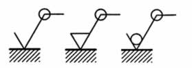
Meaning of the Basic Symbol
The basic “V” mark in the surface finish symbol indicates that the surface has been machined.
Adding a Roughness Value
The Ra value added above the symbol indicates the maximum allowed surface roughness in microns.
Machining Allowance Information
Additional notes added to a surface finish symbol can also indicate the material-removal allowance that must be left on that surface.
Information Added to Surface Finish Symbols
a) Roughness values in μm together with the Ra symbol, or roughness symbols together with the appropriate values in μm*
b) The production method, processing, coating, or other rules relating to the manufacturing process, etc.
c) Waviness in μm together with the relevant symbol, or the sampling length in mm — when in accordance with (TS6212 – ISO 4288), this value should be omitted for Ra, Ry and Rz.
d) The direction of the machining marks (lay)
e) Machining allowance (ISO 10135) f. Roughness values in μm together with symbols other than Ra
* : Roughness values other than Ra will, for now, be shown in area (f).
The various pieces of information to be added to the graphic symbol according to the surface condition are specified in the TS standard as follows.

Dimensions of the Surface Finish Symbol


How Surface Finish Symbols Are Shown


Surface Finish Symbols: Example Applications


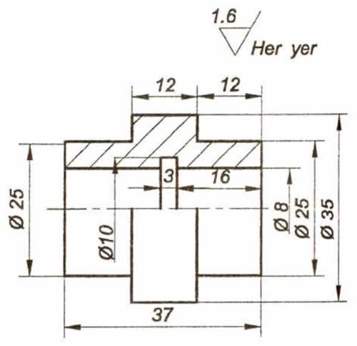


Sample Question

The figure shows a shaft with two views, whose dimensions and some surface conditions have been left out. Surface a has been ground to N6 quality, surface b has been milled to N7 quality, and surface c has been milled to N8 quality. N10 quality has been chosen for the remaining, unspecified surfaces. Based on this, place the appropriate symbols and quality grades in the corresponding locations on a 1:1 scale drawing you will make on A5 paper.
Related Questions
Even if a part’s dimensions are correct, if its surface is rough, it will not work properly with mating parts or will wear out quickly. These symbols tell the manufacturer what quality the surface needs to be machined to, ensuring the part performs its function correctly.
These two cases represent different production methods (for example, leaving a cast surface as-is versus turning it). Different symbols clearly tell the manufacturer what process that surface should (or should not) go through.
Related Posts
 Types of Sectioning in Technical Drawing? Sectioning Methods
  Technical Drawing View Extraction Examples 2
  Specifying the Manufacturing Method by Surface Roughness
  Hatching Lines in Technical Drawing
  Geometric Drawings 3 – Drawing Polygons
  How to Draw an Ellipse? Ellipse Construction.
  Fit Tolerances and Tolerance Pairs – Lesson 3
  How to Do Sectioning in Technical Drawing