
Close Menu
  • MAKİNELER ve İMALAT
    • Tools & Equipment
    • Computer-Aided Drawing
    • CAD/CAM Education
    • CNC Machine Programming
    • Casting Technologies
    • Electrical & Electronics Technologies
    • Hydraulics & Pneumatics
    • Manufacturing Processes
    • Manufacturing Technologies
    • Occupational Safety
    • Mold & Die Design
    • Solid Modeling
    • Welding Technology
    • Machine Elements
    • Mechanical Trade Drawing
    • Materials Science
    • Automotive & Vehicle Technologies
    • Robotics Technologies
    • Health Technologies
    • Defense & Aerospace Technologies
    • Descriptive Geometry
    • Technical Drawing
    • Software & Hardware Technologies
    • Innovative Manufacturing Methods
  • TEKNOLOJİ ve YAŞAM
    • OTOMOBİLLER ve TAŞIT
      • Vehicle & Engine Knowledge
      • Safe Driving
      • Sürüş Destek Sistemleri
    • Genel Kültür
      • Movies & TV Shows
      • Görsel ve Grafik Sanat
      • Books & Literature
      • Music
      • Sports
      • History
      • History of Technology
    • GÜNDELİK YAŞAM TEKNOLOJİLERİ
    • Hobbies & Entertainment
    • Internet Technologies
    • Health
    • Mobile Technologies
Makine Eğitimi
  • Machines & Manufacturing
    Machine Elements
    Hydraulics & Pneumatics
    Technical Drawing
    Computer-Aided Design & Manufacturing
    Basic Manufacturing Processes
    Manufacturing Processes
    Industry Technologies
    Other Technical Courses
    Motion & Power Transmission
    Simple Machines
    Chains & Sprockets
    Shafts & Journals
    Gears
    Cams
    Couplings
    Belts & Pulleys
    Springs
    Bearings
    Keys
    Fastening Joining
    Retaining Rings
    Screws, Bolts & Nuts
    Cotter Pins
    Flanges
    Welding
    Rivets
    Pins & Bolts
    Washers
    Calculators
    Gear Ratio Calculator
    Spring Constant Calculator
    Belt Pulley Ratio Calculator
    Other Machine Elements
    Slides & Linear Guides
    Brakes
    Flywheels
    Clamps
    Shock Absorbers
    Gaskets & O-Rings
    Seals & Sealing Elements
    Hydraulics
    Introduction to Hydraulics & Principles
    Hydraulic Systems & Applications
    Accumulators
    Filters
    Motors
    Pumps
    Valves
    Pneumatics
    Introduction to Pneumatics & Principles
    Pneumatic Systems & Applications
    Pneumatic Circuit Components
    Valves
    Cylinders
    Silencers
    Motors
    Compressors
    Dryers
    Conditioning Units
    Common Topics & Maintenance
    Hydraulic & Pneumatic Maintenance
    Study Notes, Exams & Tests
    Technical Drawing
    Introduction to Technical Drawing
    Geometric Drawings
    Perspective & Projection
    Orthographic Views
    Dimensioning
    Sectioning
    Assembly & Detail Drawings
    Tolerances
    Surface Finish Symbols
    Mechanical Engineering Drawing
    Screws, Bolts & Nuts
    Pulley Drawings
    Gear Drawings
    Shafts & Journals
    Bearing Drawings
    Pins & Bolts
    Spring Drawings
    Welds in Technical Drawing
    Washers
    Cotter Pins
    Technical Drawing Exercises
    Mechanical Drawing Exercises
    Gear Exercises
    View Extraction Exercises
    Pulley Exercises
    Pin & Bolt Exercises
    Threaded Fastening Exercises
    Descriptive Geometry
    Computer-Aided Drawing
    AutoCAD Drawing Lessons
    Solid Modeling & Animation
    Solid Model Drawing Files
    Solid Model Assembly Examples
    Solid Model Drawing Lessons
    3D CAD Software Reviews
    Solid Modeling Exercises
    CNC Programming
    CAM
    Measurement & Inspection
    Dial Indicators
    Calipers
    Gauges
    Micrometers
    Materials Science
    Steels
    Cast Iron
    Aluminum
    Plastics
    Material Testing & Hardness Measurement
    Occupational Safety
    Workshop Safety
    Safety When Working With Electricity
    Machine Safety Rules
    Hand Operations
    Filing
    Marking
    Cutting Operations
    Reaming
    Tapping
    Threading With a Die
    Drill Bit Sharpening
    Working With Machines
    Basic Turning Operations
    Basic Milling Operations
    Shaper Machine
    Machining
    Turning
    Milling
    Grinding
    Innovative Manufacturing Methods
    EDM (Electrical Discharge Machining)
    Laser Machining
    Waterjet Machining
    3D Printing
    3D Scanners
    Welding
    Rolling
    Casting
    Mold & Die Design
    Mechanical & Hydraulic Presses
    Blanking & Piercing Dies
    Bending Dies
    Drawing Dies
    Plastic Injection Molds
    Extrusion Dies
    Compound Dies
    Progressive Dies
    Blow Molds
    Spinning Dies
    Spray Molds
    Manufacturing of Machine Parts
    Automotive & Vehicle Technologies
    Motor Vehicle Manufacturing
    Raw Material Production
    History of Technology
    Health & Medical Technologies
    Defense & Aerospace
    Robotics Technologies
    Software & Hardware Technologies
    Mechanics - Strength of Materials
    Physics Topics
  • Technology & Life
    Hobbies & Entertainment
    Sports
    Music
    Vehicle & Engine Knowledge
    Vehicle Maintenance & Repair
    Safe Driving
    Driver Assistance Systems
    History
    Movies & TV Shows
    Books & Literature
    Computers & Internet
    Computer Tips
    Software Reviews
    Hardware & Peripherals
    Practical & Safe Internet Use
    Visual & Graphic Art
    Mobile Technologies
    Travel
    Science
    Health
    First Aid Knowledge
    Everyday Technologies
Makine Eğitimi
Home»Technical Drawing»Fit Tolerances and Tolerance Pairs – Lesson 3
29 August 2026

Fit Tolerances and Tolerance Pairs – Lesson 3

Fit Tolerances and Tolerance Pairs - Lesson 3

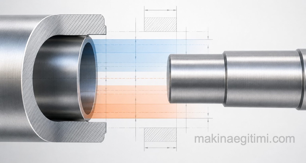
This article, relevant to technical drawing and manufacturing processes courses, covers tolerance pairs and fit tolerances. The maximum and minimum sizes that two mating machine parts need to have in order to work together as intended are expressed with tolerance pairs.

  • Fit Tolerances
  • Tolerance Pairs
    • Clearance Fit Tolerance Pairs
    • Interference (tight) fit tolerances
    • Press-fit tolerances

Fit Tolerances

The tolerance on the dimensions that let two machine parts work together determines under what conditions the two parts will operate together. These conditions range from very loose to very tight.

  • The zero-clearance position “H” is denoted with an upper- or lowercase letter.
  • Upper- or lowercase letters from “A” to “G” are used for clearance fits,
  • Upper- or lowercase letters from “J” to “Z” are used for interference (tight) fits.

(Note: the upper- or lowercase letters I, L, O, Q are not used in tolerance notation)

preferred fits tolerances. Hole and shaft systems. Engineering referance chart

Tolerance Pairs

In the ISO tolerance system, fits obtained by mating various shafts to the same standard hole, or various holes to the same standard shaft, form the fit groups. Accordingly, in the hole-basis system there are the groups H6, H7, H8, H9, H10, H11, H12, and in the shaft-basis system there are h5, h6, h8, h9, h10, h11, and h12.

In machine building, H6, H7, H8, H11 and h5, h6, h8, h9, and h11 from these fit groups generally cover all needs.

Clearance Fit Tolerance Pairs

H7-h6: Used for machine parts assembled with lubricated surfaces. Example: pulley hubs, retaining collars, clutches, and moving machine-tool parts that need to be replaced frequently.

H7-g6: Sliding fit tolerance. Example: gears, clutches, connecting-rod bearings, pistons that need to move axially

H8-h9: Easy running fit. Example: transmission shaft retaining collars, belt pulleys, gears, clutches, etc.

H7-f7: Running fit tolerance. For example: machine tool main bearings, crankshafts

H7-e8: Tolerance for clearance fits. Example: fits that need to keep moving freely under heat

H7-d9: Tolerance pair used for very loose (large clearance) fits

Interference (tight) fit tolerances

H7-j6: A “tap-in” fit tolerance: easy tight fits assembled by tapping with a wooden mallet. Example: belt pulleys, gears, hand wheels, bearing bushings, etc.

H7-k6: Belongs to the easy hammer-fit type of fit tolerance: for example, pulleys, bearing inner races, hand wheels, etc.

H8-n6: A hard hammer-fit type of fit tolerance: for example, pulleys, clutches, couplings, etc.

H7-n6: Tolerance pair used for fits assembled by pressing: example — pulleys that will never be removed again, rotors pressed onto a motor shaft, gears that will be pressed onto a journal, bushings pressed into hubs, and similar fitting operations.

Press-fit tolerances

These are fits made by pressing, or by heating and expanding the socket, and that will never be disassembled again.

H7-r6: Fits that won’t shift under a moderate, constant force. Example: pressing a steel band onto a cast-iron hub, bushings pressed into connecting-rod bearings, etc.

H8-u8: Fits that won’t shift under a large, constant force.

Related Posts
Fit Tolerance Simulator Fit Tolerance Simulator Hole and Shaft Tolerances Hole and Shaft Tolerances Geometrik Çizimler 3 – Çokgen Çizme Geometric Drawings 3 – Drawing Polygons Teknik Resimde Kesit Alma Nasıl Yapılır How to Do Sectioning in Technical Drawing Hatching Lines in Technical Drawing Hatching Lines in Technical Drawing Introduction to Surface Finish Symbols Introduction to Surface Finish Symbols Ölçü Toleranslarının Teknik Resimde Gösterilmesi Showing Dimensional Tolerances in Technical Drawing How Is Dimensioning Done? Rules of Dimensioning How Is Dimensioning Done? Rules of Dimensioning
Tolerances in Technical Drawing
Share. Facebook Twitter WhatsApp Tumblr Email Telegram Copy Link

Leave A Reply Cancel Reply

The Black Death: How Did a Pandemic Bring About the End of the Middle Ages?
Ways to Tell If Your Car Battery Is Dead
  • Contact
  • Terms of Service
  • Privacy & Cookie Policy

Type above and press Enter to search. Press Esc to cancel.