Twist Drills
In the machine education manufacturing operations lessons category, this article’s topic will be twist drills. We’ll cover the parts of twist drills, the angles of twist drills, their precision, the types of twist drills, and sharpening twist drills / thinning their web. The article’s content menu is given below:
Types of Twist Drills
As is well known, all materials used in industry have different properties from one another. These different properties in metal materials mean the cutting tools used to machine them also need to carry some differences.
For a drill to cut well, the chips it produces need to flow away smoothly. Easy chip flow depends on the drill’s helix angle. For this reason, twist drills are made with three different helix angles. These are:
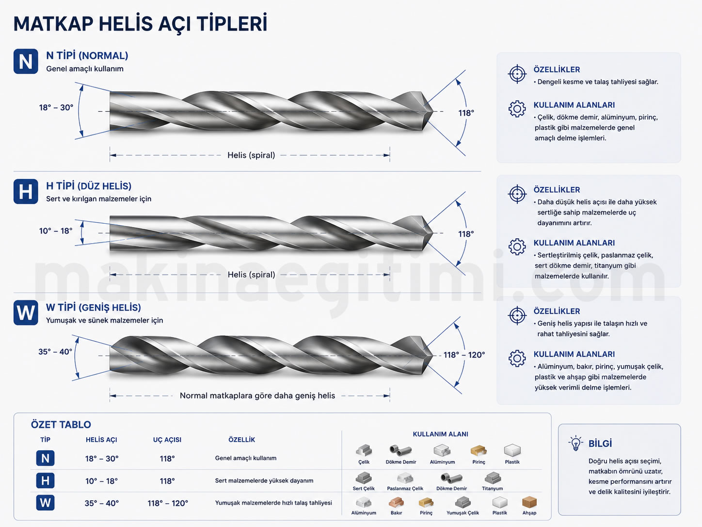
Types of twist drills:
- Type N: For normal-hardness steels. Helix angle is between 18-30 degrees, and point angle is 118 degrees.
- Type H: For hard steels. Helix angle is between 10-15 degrees, and point angle is 118 degrees.
- Type W: For soft materials. Helix angle is 35-40 degrees, and point angle is between 118-130 degrees.
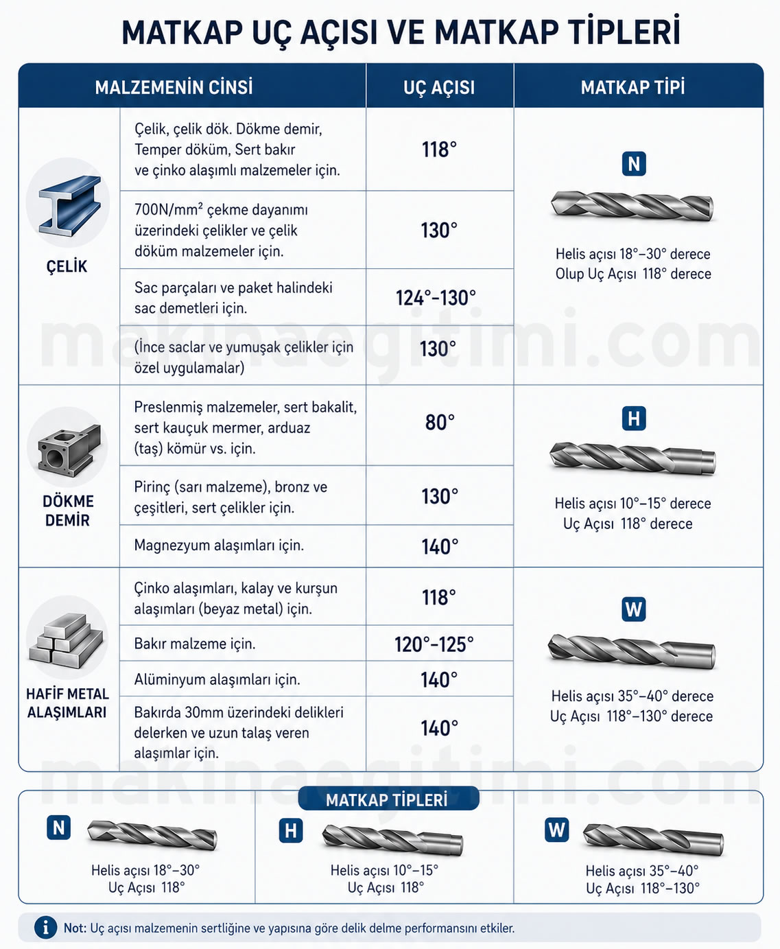
The point angles of drills also change depending on the type of material. If the drill’s point angle is large, the cutting edges are shorter and heat up less during cutting. If the drill’s point angle is narrow, the cutting edges are longer, the drill heats up a lot during drilling, and as a result loses its cutting ability quickly.
The Angles That Allow Twist Drills to Cut

For a drill to cut easily under normal conditions, its edges are ground with specific angles. The values of these angles vary depending on the type of material to be drilled.
Point Angle on Twist Drills:
Twist drills are ground with a pointed tip since they cut by plunging into the work. The pointedness of the drill’s tip is provided by the point angle. The drill’s point angle is set at 118 degrees for drilling steel materials, and 130 degrees for soft and brittle materials.
Drill Rake Angle (Helix Angle):
This is the angle that forms the drill’s helical flute. Since the chips produced during cutting exit by following this flute, this angle is also called the rake angle. The drill’s rake angle, that is, its helix angle, varies depending on the type of material being drilled. It’s given as 19-40 degrees for standard manufacturing steels, 10-19 degrees for hard and brittle materials, and 27-45 degrees for soft materials. The helix angle is set by the manufacturer of the drill. It’s not possible to change this angle. This angle can only be changed, in very necessary cases, by grinding the drill’s rake face.
Clearance Angle on Twist Drills:
This is the angle given to prevent the back surface of the drill’s cutting edges from rubbing against the cut surface while drilling a hole. The clearance angle is generally 12 degrees, and it doesn’t just prevent friction — it also helps the drill cut well. When this angle is too small, the amount of friction increases; when it’s too large, the cutting edge becomes thin. This causes the drill’s edges to break and dull quickly. For this reason, the clearance angle also needs to be set appropriately for the type of material being drilled.
Drill Lip Angle (Secondary Cutting Edge Angle):
The drill’s lip angle is the angle that the edge formed by grinding the two clearance surfaces makes with the drill’s axis. The value of the lip angle can be affected by how the drill is sharpened. When sharpening a drill, care must be taken to form the lip with perfect accuracy. The drill’s lip doesn’t cut in the full sense — it instead scrapes, letting the drill plunge into the work. For this reason, the drill’s lip is called the secondary cutting edge. The angle the secondary cutting edge makes with the drill axis should be 55 degrees.
Parts of Twist Drills
Shank: The part of the drill that fits into the tapered hole in the drilling machine’s spindle and into the chuck. At the end of a taper-shank drill, there’s a tang matching the slot cut into the machine spindle. This part prevents the drill from rotating inside the spindle and allows the drill to be easily removed with a drift. Body: The section of the drill where the helical flutes are located is called the body.
Helical Flutes: These are the flutes cut in a helical shape around the body. They form the cutting edges, allow the chips produced during cutting to be ejected outward, and let cutting fluid reach the drill’s tip.
Drill Point: This is the cutting portion of the drill, shaped at a suitable angle. The cutting edges are obtained by grinding the point.
Drill Flank: This is the surface behind the cutting edge.
Drill Cutting Edges (Lips): These are the drill’s cutting edges.
Drill Margin: This is a narrow surface running along the helical flutes. The drill’s true diameter is the distance between opposite margins. The margin reduces the friction that occurs between the drill and the workpiece.
Chisel Point (Dead Center): This is where the two cutting edges meet when a drill is well ground.
Drill Web: This is the narrow section left between the helical flutes, and it thickens going from the tip toward the shank.

Precision of Twist Drills
The diameter dimensions of twist drills are made to h8 tolerance precision. In other words, when a hole is drilled with any twist drill that we assume is perfectly sharpened, that hole’s diameter can be larger than the drill’s diameter by the numerical value of the h8 tolerance.
h8 tolerance takes different values depending on diameter groups. Drill diameters taper down slightly, by about 0.02-0.08 mm per 100 mm of length, going from the tip toward the shank — in other words, drill diameters gradually narrow and become tapered toward the shank. The purpose of this is to prevent the drill’s margin from rubbing against the hole’s surface as the hole gets deeper. For this reason, as twist drills get shorter (from repeated resharpening), their diameters also shrink by a very small amount. Holes drilled with shortened drills can come out with a smaller diameter than the true size. This difference can be up to 0.08 mm over a 100 mm length.
Sharpening Twist Drills
Besides inevitable wear, at very high cutting speeds the cutting corners of twist drills can wear additionally, and at very high feed rates the chisel edge can wear as well. Wear is especially high on incorrectly sharpened drills.
So that the drill’s tip isn’t too weak, the diameter of the chisel edge should be at least 1/10 of the drill’s diameter. The feed force can be reduced by roughly half by thinning the chisel edge.
For detailed information, see: Drill Bit Sharpening
Twist Drills with a Thinned Web
To strengthen a drill, the web is thickened as it approaches the shank. On drills with a diameter of 20mm or less, this may not be easily noticeable. But on large-diameter drills, as the drill gets shorter from resharpening, the tip will widen. In this case, the drill will have much more difficulty plunging into the workpiece and will burn. To eliminate this issue, the drill’s web needs to be thinned; a narrow grinding wheel should be used for this task, grinding equal amounts from both sides while leaving the center in place — the web shouldn’t be thinned unnecessarily, weakening the drill.
Helical Flute Design
The helical flutes of twist drills allow chips formed during drilling to be ejected out of the hole.
Standard Point Angle
For general-purpose twist drills, the most commonly used point angle is 118 degrees.
Material Type Selection
HSS (high speed steel) drills offer a balance of durability and cost in standard applications.
Related Questions
Materials of different hardness need different helix angles for efficient chip flow. A lower helix angle for hard steels and a higher one for soft materials provides the most efficient cutting and chip evacuation for each material type.
The helix angle determines how easily the cut chips can travel upward along the drill’s flutes. An unsuitable angle can cause chips to jam in the flute, leading to the drill breaking or a drop in cutting performance.
Related Posts