Close Menu
  • MAKİNELER ve İMALAT
    • Tools & Equipment
    • Computer-Aided Drawing
    • CAD/CAM Education
    • CNC Machine Programming
    • Casting Technologies
    • Electrical & Electronics Technologies
    • Hydraulics & Pneumatics
    • Manufacturing Processes
    • Manufacturing Technologies
    • Occupational Safety
    • Mold & Die Design
    • Solid Modeling
    • Welding Technology
    • Machine Elements
    • Mechanical Trade Drawing
    • Materials Science
    • Automotive & Vehicle Technologies
    • Robotics Technologies
    • Health Technologies
    • Defense & Aerospace Technologies
    • Descriptive Geometry
    • Technical Drawing
    • Software & Hardware Technologies
    • Innovative Manufacturing Methods
  • TEKNOLOJİ ve YAŞAM
    • OTOMOBİLLER ve TAŞIT
      • Vehicle & Engine Knowledge
      • Safe Driving
      • Sürüş Destek Sistemleri
    • Genel Kültür
      • Movies & TV Shows
      • Görsel ve Grafik Sanat
      • Books & Literature
      • Music
      • Sports
      • History
      • History of Technology
    • GÜNDELİK YAŞAM TEKNOLOJİLERİ
    • Hobbies & Entertainment
    • Internet Technologies
    • Health
    • Mobile Technologies
Makine Eğitimi
  • Machines & Manufacturing
    Machine Elements
    Hydraulics & Pneumatics
    Technical Drawing
    Computer-Aided Design & Manufacturing
    Basic Manufacturing Processes
    Manufacturing Processes
    Industry Technologies
    Other Technical Courses
    Motion & Power Transmission
    Simple Machines
    Chains & Sprockets
    Shafts & Journals
    Gears
    Cams
    Couplings
    Belts & Pulleys
    Springs
    Bearings
    Keys
    Fastening Joining
    Retaining Rings
    Screws, Bolts & Nuts
    Cotter Pins
    Flanges
    Welding
    Rivets
    Pins & Bolts
    Washers
    Calculators
    Gear Ratio Calculator
    Spring Constant Calculator
    Belt Pulley Ratio Calculator
    Other Machine Elements
    Slides & Linear Guides
    Brakes
    Flywheels
    Clamps
    Shock Absorbers
    Gaskets & O-Rings
    Seals & Sealing Elements
    Hydraulics
    Introduction to Hydraulics & Principles
    Hydraulic Systems & Applications
    Accumulators
    Filters
    Motors
    Pumps
    Valves
    Pneumatics
    Introduction to Pneumatics & Principles
    Pneumatic Systems & Applications
    Pneumatic Circuit Components
    Valves
    Cylinders
    Silencers
    Motors
    Compressors
    Dryers
    Conditioning Units
    Common Topics & Maintenance
    Hydraulic & Pneumatic Maintenance
    Study Notes, Exams & Tests
    Technical Drawing
    Introduction to Technical Drawing
    Geometric Drawings
    Perspective & Projection
    Orthographic Views
    Dimensioning
    Sectioning
    Assembly & Detail Drawings
    Tolerances
    Surface Finish Symbols
    Mechanical Engineering Drawing
    Screws, Bolts & Nuts
    Pulley Drawings
    Gear Drawings
    Shafts & Journals
    Bearing Drawings
    Pins & Bolts
    Spring Drawings
    Welds in Technical Drawing
    Washers
    Cotter Pins
    Technical Drawing Exercises
    Mechanical Drawing Exercises
    Gear Exercises
    View Extraction Exercises
    Pulley Exercises
    Pin & Bolt Exercises
    Threaded Fastening Exercises
    Descriptive Geometry
    Computer-Aided Drawing
    AutoCAD Drawing Lessons
    Solid Modeling & Animation
    Solid Model Drawing Files
    Solid Model Assembly Examples
    Solid Model Drawing Lessons
    3D CAD Software Reviews
    Solid Modeling Exercises
    CNC Programming
    CAM
    Measurement & Inspection
    Dial Indicators
    Calipers
    Gauges
    Micrometers
    Materials Science
    Steels
    Cast Iron
    Aluminum
    Plastics
    Material Testing & Hardness Measurement
    Occupational Safety
    Workshop Safety
    Safety When Working With Electricity
    Machine Safety Rules
    Hand Operations
    Filing
    Marking
    Cutting Operations
    Reaming
    Tapping
    Threading With a Die
    Drill Bit Sharpening
    Working With Machines
    Basic Turning Operations
    Basic Milling Operations
    Shaper Machine
    Machining
    Turning
    Milling
    Grinding
    Innovative Manufacturing Methods
    EDM (Electrical Discharge Machining)
    Laser Machining
    Waterjet Machining
    3D Printing
    3D Scanners
    Welding
    Rolling
    Casting
    Mold & Die Design
    Mechanical & Hydraulic Presses
    Blanking & Piercing Dies
    Bending Dies
    Drawing Dies
    Plastic Injection Molds
    Extrusion Dies
    Compound Dies
    Progressive Dies
    Blow Molds
    Spinning Dies
    Spray Molds
    Manufacturing of Machine Parts
    Automotive & Vehicle Technologies
    Motor Vehicle Manufacturing
    Raw Material Production
    History of Technology
    Health & Medical Technologies
    Defense & Aerospace
    Robotics Technologies
    Software & Hardware Technologies
    Mechanics - Strength of Materials
    Physics Topics
  • Technology & Life
    Hobbies & Entertainment
    Sports
    Music
    Vehicle & Engine Knowledge
    Vehicle Maintenance & Repair
    Safe Driving
    Driver Assistance Systems
    History
    Movies & TV Shows
    Books & Literature
    Computers & Internet
    Computer Tips
    Software Reviews
    Hardware & Peripherals
    Practical & Safe Internet Use
    Visual & Graphic Art
    Mobile Technologies
    Travel
    Science
    Health
    First Aid Knowledge
    Everyday Technologies
Makine Eğitimi
Home»Manufacturing Processes»Knurling. The Knurling Process on a Lathe
29 August 2026

Knurling. The Knurling Process on a Lathe

Tornada Tırtıl çekme işlemi

Knurling

All knurls made in manufacturing shops are classified as fine, medium, coarse, straight, and diamond. The knurling tool consists of small hardened rollers with a knurled pattern on their surface.

  • Knurling
    • Knurling Operation on a Lathe
    • Knurling Process Order
    • Video of How Knurling Is Done
    • Video of How Knurling Is Done 2
    • Knurling Questions
  • Related Questions

Knurling: The process of adding indentations and ridges to a part’s surface using tools called knurls.
Parts that will be gripped by hand, turned, or adjusted, such as nuts, screws, or tool handles, are easier to work with if they are knurled. For example, like a fitness dumbbell bar.
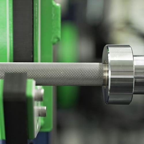
We can provide a safer way to work by knurling tool handles that could otherwise cause accidents if held with sweaty or oily hands.
We can perform this knurling process on such cylindrical surfaces on lathes.
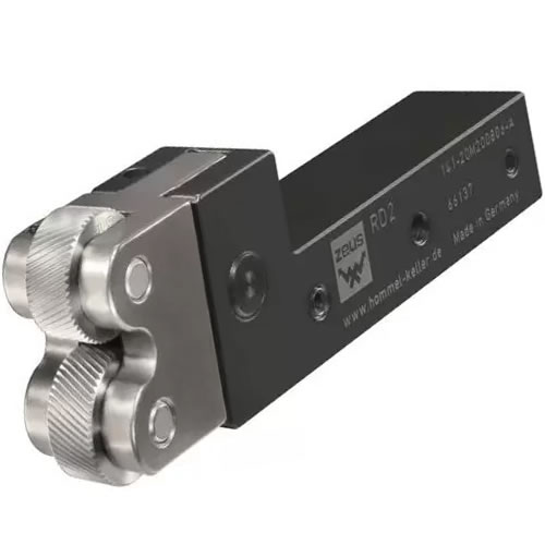
knurling tool holder

For this operation, we’ll need a knurling tool holder. A knurling tool holder is a piece of equipment with freely rotating knurl wheels mounted on it.

types of knurling tool holders single wheel 2-wheel adjustable

Knurling tool holders come in single-wheel, 2-wheel, or more-wheel adjustable types.

Knurl wheels also come in different types depending on preference: coarse, medium, fine tooth, straight tooth, and diamond tooth.
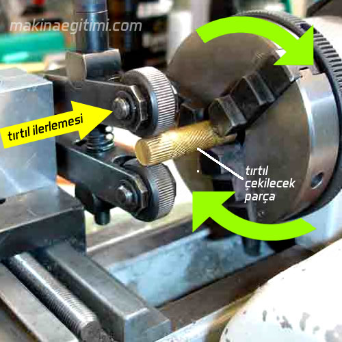
The principle of the knurling operation on a lathe is that the knurl wheels, in contact with a cylindrical part rotating on its own axis at low speed, advance slowly parallel to the part’s axis and form patterns on the part.

Knurling Operation on a Lathe

When starting the knurling process, care must be taken to ensure both wheels form the diamond pattern with matching, equal marks. When the knurling process begins, the wheels should be pressed firmly against the part; once you’re sure they’re making a mark, the pressure should be reduced.
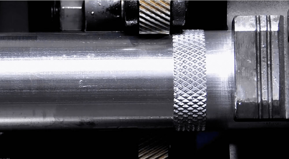
knurling operation on a lathe

The knurled section should be clean, sharp, and diamond-patterned as shown in the figure. 

If it starts well, the knurling process usually goes well all the way to the end with a medium or fairly large feed. If the diamond pattern doesn’t start well, start from another section on the part; if the result is good this time, the defective section can be corrected by passing over it again.

Knurling process animation

Knurling Process Order

  1. The workpiece is mounted as short as possible either between two centers or between the chuck and a center, and the length of the knurl is marked.
  2.  The knurling tool holder is mounted in the tool post at center height, at an angle of about 5 degrees toward the left.
  3. The lathe spindle is set to a low, suitable speed.

4- The knurl is brought into contact with the surface of the workpiece and advanced by about 0.1 to 0.2 mm.

5- Once knurl marks are seen forming on the surface of the workpiece, the carriage is moved slowly. (Automatic feed should preferably be engaged)

6- When the end of the knurled section is reached, the machine is stopped and the spindle is reversed. This operation is similar to thread cutting on a lathe.

7- During the operation, oil should be continuously applied to the surface of the workpiece with a brush or oil can.

Video of How Knurling Is Done

Video of How Knurling Is Done 2

Knurling Questions

Question: Does the diameter of the part grow during knurling?

Answer: At the end of the knurling process, the diameter of the part grows slightly.
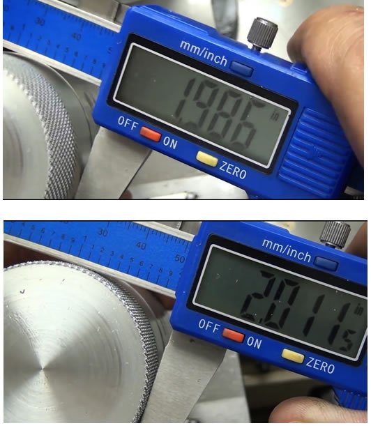
diameter change after knurling
The diameter difference between unknurled and knurled surfaces shows that knurling increases the part’s diameter.

Question: Can automatic feed be used for knurling? Is oil used?

Answer: Automatic feed can be used for knurling — one or two passes are enough for this. Regardless of the material, oil is used while knurling.
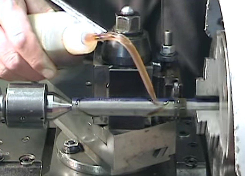
use of oil in knurling
Regardless of the material, oil is used during the knurling process

In this article, we covered how knurling is done. See you in new articles.

Purpose of the Knurl Pattern


Knurling is done to give gripping surfaces a patterned texture that prevents slipping.

Straight and Diamond Knurl


Knurls can be cut in straight-line or crossed (diamond) patterns, in different geometries depending on the intended use.

Plastic Deformation


Knurling is a process that plastically forms the material without removing any chips.

Related Questions

A flat surface can easily slip when gripped with a sweaty or oily hand. Knurling adds texture to the surface, preventing the hand from slipping and allowing a more secure grip on the tool.

The knurl wheels are pressed against the surface of the rotating part, plastically deforming the metal rather than cutting it. This pressure forms an indented, ridged pattern on the surface, producing the desired knurled appearance.

Related Posts

Cutting Speed – RPM Calculator Cutting Speed – RPM Calculator Tornada Kesme Hızı ve Devir Sayısı Cutting Speed and RPM on a Lathe cutting large-lead helical flutes Cutting Large-Lead Helical Flutes on a Milling Machine Mastar Nedir Neden Kullanılır? What Is a Gauge. Why Is It Used? Gear Making by the Hobbing Method Gear Making by the Hobbing Method Workpiece Clamping Methods on a Milling Machine Workpiece Clamping Methods on a Milling Machine Work Instructions for a Cylindrical Grinding Machine Work Instructions for a Cylindrical Grinding Machine Types of Gauges Lesson Information About Types of Gauges
Basic Turning Operations Turning
Share. Facebook Twitter WhatsApp Tumblr Email Telegram Copy Link

Leave A Reply Cancel Reply

What Is a Catalytic Converter, What Is It For?
Robotic Welding Applications on the Automotive Assembly Line
  • Contact
  • Terms of Service
  • Privacy & Cookie Policy

Type above and press Enter to search. Press Esc to cancel.