Close Menu
  • MAKİNELER ve İMALAT
    • Tools & Equipment
    • Computer-Aided Drawing
    • CAD/CAM Education
    • CNC Machine Programming
    • Casting Technologies
    • Electrical & Electronics Technologies
    • Hydraulics & Pneumatics
    • Manufacturing Processes
    • Manufacturing Technologies
    • Occupational Safety
    • Mold & Die Design
    • Solid Modeling
    • Welding Technology
    • Machine Elements
    • Mechanical Trade Drawing
    • Materials Science
    • Automotive & Vehicle Technologies
    • Robotics Technologies
    • Health Technologies
    • Defense & Aerospace Technologies
    • Descriptive Geometry
    • Technical Drawing
    • Software & Hardware Technologies
    • Innovative Manufacturing Methods
  • TEKNOLOJİ ve YAŞAM
    • OTOMOBİLLER ve TAŞIT
      • Vehicle & Engine Knowledge
      • Safe Driving
      • Sürüş Destek Sistemleri
    • Genel Kültür
      • Movies & TV Shows
      • Görsel ve Grafik Sanat
      • Books & Literature
      • Music
      • Sports
      • History
      • History of Technology
    • GÜNDELİK YAŞAM TEKNOLOJİLERİ
    • Hobbies & Entertainment
    • Internet Technologies
    • Health
    • Mobile Technologies
Makine Eğitimi
  • Machines & Manufacturing
    Machine Elements
    Hydraulics & Pneumatics
    Technical Drawing
    Computer-Aided Design & Manufacturing
    Basic Manufacturing Processes
    Manufacturing Processes
    Industry Technologies
    Other Technical Courses
    Motion & Power Transmission
    Simple Machines
    Chains & Sprockets
    Shafts & Journals
    Gears
    Cams
    Couplings
    Belts & Pulleys
    Springs
    Bearings
    Keys
    Fastening Joining
    Retaining Rings
    Screws, Bolts & Nuts
    Cotter Pins
    Flanges
    Welding
    Rivets
    Pins & Bolts
    Washers
    Calculators
    Gear Ratio Calculator
    Spring Constant Calculator
    Belt Pulley Ratio Calculator
    Other Machine Elements
    Slides & Linear Guides
    Brakes
    Flywheels
    Clamps
    Shock Absorbers
    Gaskets & O-Rings
    Seals & Sealing Elements
    Hydraulics
    Introduction to Hydraulics & Principles
    Hydraulic Systems & Applications
    Accumulators
    Filters
    Motors
    Pumps
    Valves
    Pneumatics
    Introduction to Pneumatics & Principles
    Pneumatic Systems & Applications
    Pneumatic Circuit Components
    Valves
    Cylinders
    Silencers
    Motors
    Compressors
    Dryers
    Conditioning Units
    Common Topics & Maintenance
    Hydraulic & Pneumatic Maintenance
    Study Notes, Exams & Tests
    Technical Drawing
    Introduction to Technical Drawing
    Geometric Drawings
    Perspective & Projection
    Orthographic Views
    Dimensioning
    Sectioning
    Assembly & Detail Drawings
    Tolerances
    Surface Finish Symbols
    Mechanical Engineering Drawing
    Screws, Bolts & Nuts
    Pulley Drawings
    Gear Drawings
    Shafts & Journals
    Bearing Drawings
    Pins & Bolts
    Spring Drawings
    Welds in Technical Drawing
    Washers
    Cotter Pins
    Technical Drawing Exercises
    Mechanical Drawing Exercises
    Gear Exercises
    View Extraction Exercises
    Pulley Exercises
    Pin & Bolt Exercises
    Threaded Fastening Exercises
    Descriptive Geometry
    Computer-Aided Drawing
    AutoCAD Drawing Lessons
    Solid Modeling & Animation
    Solid Model Drawing Files
    Solid Model Assembly Examples
    Solid Model Drawing Lessons
    3D CAD Software Reviews
    Solid Modeling Exercises
    CNC Programming
    CAM
    Measurement & Inspection
    Dial Indicators
    Calipers
    Gauges
    Micrometers
    Materials Science
    Steels
    Cast Iron
    Aluminum
    Plastics
    Material Testing & Hardness Measurement
    Occupational Safety
    Workshop Safety
    Safety When Working With Electricity
    Machine Safety Rules
    Hand Operations
    Filing
    Marking
    Cutting Operations
    Reaming
    Tapping
    Threading With a Die
    Drill Bit Sharpening
    Working With Machines
    Basic Turning Operations
    Basic Milling Operations
    Shaper Machine
    Machining
    Turning
    Milling
    Grinding
    Innovative Manufacturing Methods
    EDM (Electrical Discharge Machining)
    Laser Machining
    Waterjet Machining
    3D Printing
    3D Scanners
    Welding
    Rolling
    Casting
    Mold & Die Design
    Mechanical & Hydraulic Presses
    Blanking & Piercing Dies
    Bending Dies
    Drawing Dies
    Plastic Injection Molds
    Extrusion Dies
    Compound Dies
    Progressive Dies
    Blow Molds
    Spinning Dies
    Spray Molds
    Manufacturing of Machine Parts
    Automotive & Vehicle Technologies
    Motor Vehicle Manufacturing
    Raw Material Production
    History of Technology
    Health & Medical Technologies
    Defense & Aerospace
    Robotics Technologies
    Software & Hardware Technologies
    Mechanics - Strength of Materials
    Physics Topics
  • Technology & Life
    Hobbies & Entertainment
    Sports
    Music
    Vehicle & Engine Knowledge
    Vehicle Maintenance & Repair
    Safe Driving
    Driver Assistance Systems
    History
    Movies & TV Shows
    Books & Literature
    Computers & Internet
    Computer Tips
    Software Reviews
    Hardware & Peripherals
    Practical & Safe Internet Use
    Visual & Graphic Art
    Mobile Technologies
    Travel
    Science
    Health
    First Aid Knowledge
    Everyday Technologies
Makine Eğitimi
Home»Manufacturing Processes»Johnson Gauge Blocks (Johansson Gauge Blocks) and Their Use
29 August 2026

Johnson Gauge Blocks (Johansson Gauge Blocks) and Their Use

Johnson Gauge Blocks and their use

This article, part of Machine Education’s measurement-and-control topics for manufacturing processes, is about Johansson gauge blocks (also called Johnson gauges).

  • Johansson Gauge Blocks
    • Johnson gauge blocks by purpose
    • How is a Johansson gauge block used?
    • Checking Shaft Dimensions with Johansson Gauge Blocks
    • Checking Hole Dimensions with Johansson Gauge Blocks
  • Related Questions

Johansson Gauge Blocks

Johansson gauge blocks are rectangular-prism-shaped steel parts, specially hardened and with extremely finely finished surfaces. They were developed by the Swedish inventor Carl Edvard Johansson. Two opposite faces of each block are made perfectly parallel and lapped through an extremely precise, fine finishing process. Thanks to the parallelism of the measuring surfaces and the superior workmanship in their manufacture, when several are stacked together to obtain a combined dimension, they adhere to one another (wring together) under a pressure of roughly 40 kg/cm².

Video showing parallel gauge blocks being combined (above)

Johansson gauge blocks come in many different sets, in special wooden boxes. For example:

  1. A 9-piece set in 0.001 mm steps from 1.001 to 1.009 mm,
  2. A 9-piece set in 0.01 mm steps from 1.01 to 1.09 mm,
  3. A 20-piece set in 0.05 mm steps from 0.05 to 1 mm,
  4. A 9-piece set in 0.001 mm steps from 1.001 to 1.009 mm,
  5. A 9-piece set in 0.01 mm steps from 1.01 to 1.09 mm,
  6. A 9-piece set in 0.1 mm steps from 1.1 to 1.9 mm,
  7. A 9-piece set in 1 mm steps from 1 to 9 mm,
  8. A 10-piece set in 10 mm steps from 10 to 100 mm,
Johnson gauge block set, Johansson gauge box

There are also boxes with a total of 46 pieces, as well as Johnson gauge block sets with 87, 111, and 121 pieces.

Johnson gauge blocks by purpose

1 — Gauges of accuracy grade AA are the most precise and are used in metrology laboratories.

2 — Those of accuracy grade A are useful in the manufacture and inspection of precision measuring instruments.

3 — Johansson gauge blocks of accuracy grade B are used for inspecting work fixtures made for cutting tools such as mills and drills.

4 — Those of accuracy grade C are generally used in workshops for inspection and marking-out work.

How is a Johansson gauge block used?

Johnson gauge blocks, which have many uses, can also serve as limit gauges by making use of a set of accessory parts. These accessory parts come together with the Johansson blocks as a complete set inside the box. The most important part of this set is the holder frame.

how is a Johnson gauge block used

Use of the Johnson gauge block (above)

A set generally contains holder frames in three sizes. With these frames, dimensions from 0-50, 0-100, and up to 100-200 mm can be checked. The box also contains measuring jaws used for checking internal and external dimensions.
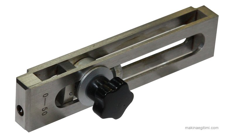
Johnson gauge block holder frame

Close-up view of the 0-50 Johansson gauge block holder frame (above)

Checking Shaft Dimensions with Johansson Gauge Blocks

Knowing how to build limit gauges using Johansson blocks with their accessory parts is important for adapting to work and working conditions in places where fork (snap) gauges and plug gauges aren’t available.

Johansson gauge block accessory set. Johnson gauge accessories

Shown above is a Johansson gauge block accessory set.
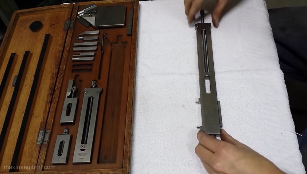
Johnson gauge blocks in use. How is a Johnson gauge block used

The image above shows the jaws being set up using the Johansson gauge block’s holder frame.

To check the dimension of a shaft, a holder frame is chosen based on the desired size. Two suitable measuring jaws are placed inside the frame, and the number of Johnson gauge blocks needed to produce the size are placed between them, and the frame’s screw is tightened.

how to use a Johansson gauge block

Checking Hole Dimensions with Johansson Gauge Blocks

For this, measuring jaws are used that come in pairs, with their measuring portions shaped like half-cylinders. The surfaces of these jaws that contact the Johnson gauge blocks are ground flat and lapped. To widen the measuring range, the thickness of the half-cylinder measuring tips is made in various sizes. When the flat faces of the two jaws making up a pair are brought together, the measuring tips form complete cylinders of, for example, 2 x 2.4 or 2 x 5 = 10 mm diameter.
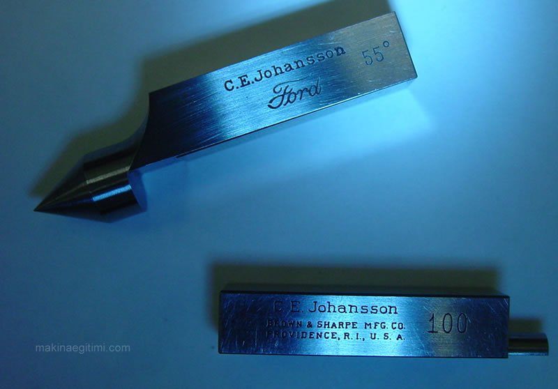
Johansson gauge block jaws

Two different types of jaws belonging to a Johansson gauge block set (above)

The hole dimension is obtained by adding together the thickness of these measuring jaws plus the Johnson gauge blocks placed between them.

By making use of Johnson gauge blocks and measuring jaws, it’s also possible to set up “go” and “no-go” limit gauges with the holder frame.

High Precision


Johansson gauge blocks are reference measuring blocks manufactured to micron-level precision.

Stackable Design


These gauge blocks can be wrung together to form combinations of the desired size, allowing many different dimensions to be produced.

Calibration Standard


Johansson gauge blocks are used as an industry-standard reference for calibrating measuring instruments.

Related Questions

Johansson gauge blocks are reference measuring blocks manufactured to micron-level precision.

These blocks are wrung together to form combinations of the desired size, allowing different dimensions to be produced.

Johansson gauge blocks are used as an industry-standard reference for calibrating measuring instruments.

Related Posts

Reamer Hole Tolerance Table Reamer Hole Tolerance Table Tornada Kare vida açma Cutting a Square Thread on a Lathe Vernier caliper simulator tool Vernier Caliper Simulator Workplace Safety When Working With an Angle Grinder Workplace Safety When Working With an Angle Grinder 1/10 1/20 1/50 Caliper Reading Practice Questions 1/10 1/20 1/50 Caliper Reading Practice Questions Circular Indexing with a Dividing Head Circular Indexing with a Dividing Head – Simple and Differential Indexing Gear Making by the Hobbing Method Gear Making by the Hobbing Method Work Instructions for a Surface Grinding Machine Work Instructions for a Surface Grinding Machine
Gauges
Share. Facebook Twitter WhatsApp Tumblr Email Telegram Copy Link

Leave A Reply Cancel Reply

Berlin Streets After World War II. July 1945
How Is a Camshaft Checked?
  • Contact
  • Terms of Service
  • Privacy & Cookie Policy

Type above and press Enter to search. Press Esc to cancel.