In this article we’ll cover general information about the facing operation on a lathe. The order of operations in facing. A video about how facing is done. Facing between centers. Using a half-center for facing.
General Information About the Facing Operation
The turning operation produced by moving the cutting tool perpendicular to the axis, against the workpiece’s rotary motion, is called FACING.
It’s done to machine the end faces of the workpiece flat and smooth, and to bring the part to the desired length.
The facing operation is what establishes the length dimensions on a part. There’s no standard machining allowance for facing. In practice, for parts cut with a saw, an allowance of 1-2 mm is left for each end, taking the saw’s cutting accuracy into account.
In facing, the turning diameter continuously grows or shrinks depending on the direction of cut. As a result, cutting speed also constantly decreases or increases. This shows that on universal lathes, facing isn’t an optimal turning operation, since cutting speed keeps changing. For this reason, when determining the spindle speed for facing, the average diameter is taken as the reference turning diameter.
In turning, the first surface machined is generally the end face. Two methods are used for facing.
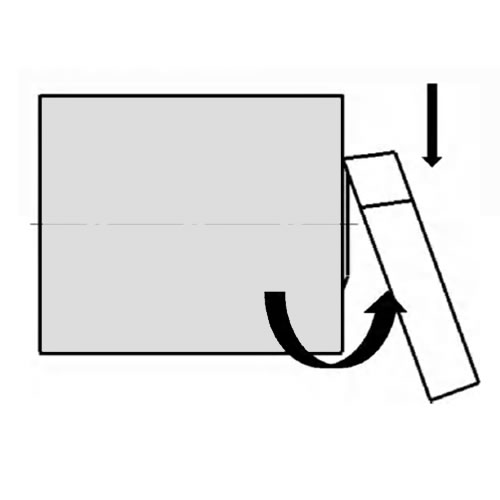
Facing from the outside toward the center is generally used for roughing.
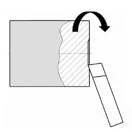
Facing from the center outward. Used for taking a fine finishing cut.
The video below shows how facing is done with the workpiece held in a chuck.
Order of Operations in Facing

Position of the cutting tool during facing
1- When a straight right-hand tool bit is selected, it should be mounted angled about 10° to the left.
2- The machine should be run at the correct speed for the cutting speed.
3- The depth of cut should be set from the cross slide.
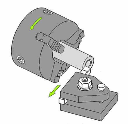

Checking Part Length Before Facing
Since parts cut with a hacksaw or any saw machine aren’t perfectly even, a workpiece is generally cut a bit longer than its final finished length. Before starting work on any part, the machinist measures it to make sure it’s long enough. If the part isn’t long enough, an unmachined section is left on both ends to show that the part is short.

Facing starts from the center
Always keep in mind that the tool bit’s job is to cut the metal, not scrape it. Don’t take too heavy a cut. Learn as quickly as possible how to judge the depth of the chip to take off the face of a given workpiece.

Facing the ends of long parts supported between centers
Surface Flatness
Facing flattens the part’s end face, creating a reference surface for subsequent operations.
Feed Direction
In facing, the tool is fed radially, either toward the center of the part or outward from the center.
Advantage of Using Centers
Mounting between centers reduces deflection (bending) when machining long parts, increasing precision.
Facing Between Centers
Setting Up the Workpiece: After carefully drilling center holes in the part’s end faces, tightly clamp the carrier (lathe dog) onto one end (place a protective piece of copper under the carrier’s screw, unless this end is unmachined). Put a drop of oil in the center hole at the other end. Place the workpiece between centers and adjust the tailstock center.
An experienced machinist first places the workpiece onto the headstock (live) center, to make sure the tail of the carrier is held in the chuck slot. Then, bringing the tailstock center up two or three times, they make sure its point enters the center hole cleanly without hitting anything.
To avoid noise, the workpiece must be set between centers neither too loose nor too tight, since the workpiece needs to rotate freely — otherwise the center point gets crushed and damaged. For this reason, it’s essential to carefully adjust the workpiece between centers. If the part isn’t too large, the machinist does this adjustment by gently working the carrier’s tail back and forth in the chuck slot. When setting the workpiece between centers, don’t try to hold the dog lengthwise or reach over the tool post. Steady the workpiece by resting your hand on the tool guard or another suitable spot.
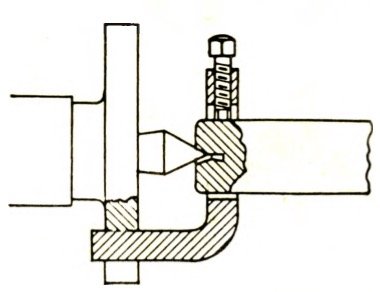
If a carrier with a larger diameter than needed is used, its tail can rest against the edges or the bottom of the chuck slot. In either position, the center won’t seat properly and the part won’t rotate correctly.
Tools Used for Facing Between Centers
A side tool bit is used for facing. There are various tool holders made by different manufacturers for mounting the bits used in this operation. The side tool bit’s cutting edge should not be set perpendicular to the workpiece’s axis; instead, it should be mounted at a slight angle, with its point angled slightly toward the face. To get a smooth, good finish, the side tool bit’s tip should be ground with a slight rounding using an oilstone, or ground so it contacts the workpiece along a short, straight edge.
This straight edge’s length should be greater than the amount of cross feed. To make sure the straight section is set perpendicular to the axis, set the tool bit by eye and then take a light facing cut. Then bring the tool bit in (feeding by hand lengthwise) until it touches the face of the part, and check whether the straight section touches the machined flat surface. If it does, the straight section is set perpendicular to the axis; if not, it’s easy to readjust the tool bit.
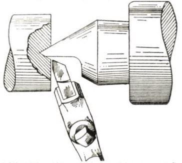
The rough cut is taken by feeding the tool bit from the workpiece’s center toward the outer edge, or from the edge toward the center. The final finishing cut is made from the center toward the edge. (If the face has a lot of stock to remove, it may be advisable to take the rough cut with the tool fed lengthwise instead — that is, removing the bulk of the material with several longitudinal hand-fed “step cuts” rather than a radial cut, for which a suitably ground cylindrical turning tool works better.)

If there are many parts to be faced, it may be advisable to check out a half-center from the tool room. But if it’s just one or two parts, or if a half-center isn’t available, the following method is used:
Set the workpiece between centers (neither too loose nor too tight); run the lathe with your right hand on the cross-feed lever and your left hand on the longitudinal feed handwheel, and bring the tool bit up to the center until only a small stub remains around the center hole. Hold the depth of cut (longitudinal feed) steady with your left hand while slowly feeding the tool bit outward, toward the edge, with your right hand — this way, facing is achieved through the cross-feed motion. The amount of chip and feed should be adjusted according to the situation.
Related Questions
Cutting speed depends on the part’s current diameter, and in facing, that diameter keeps shrinking as the tool moves toward the center. Since spindle speed is held constant, this changing diameter causes the cutting speed to keep changing too.
In this operation, the tool moves perpendicular to the part’s end face, cutting away the excess material. This both smooths the surface and brings the part to the exact desired length.
Related Posts