
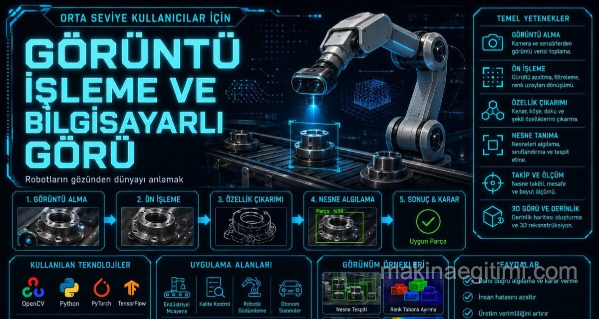
Computer vision forms the perceptual layer a robot needs to interpret camera images, recognize objects around it, estimate distances, and track its own motion. In this final part of the series, we look at the image processing techniques commonly used in robotic systems, depth-sensing methods, and deep-learning-based perception approaches.
Camera Calibration: From Image to Real World
Before pixel coordinates from a camera can be related to real-world measurements, camera calibration must be performed first. The calibration process determines the camera’s intrinsic parameters (focal length, optical center, lens distortion coefficients) and extrinsic parameters (the camera’s position and orientation relative to the robot body).
This is typically done by taking multiple photos of a checkerboard pattern with a known geometry from different angles and mathematically computing the parameters from these images. An uncalibrated camera can miscalculate the position of objects near the edges of the image, due to lens distortion that is especially pronounced in wide-angle lenses.
Classic Image Processing Techniques
Before deep-learning-based methods became widespread, and still today in applications requiring low computational power, classic image processing techniques offer solutions adequate for robotic perception. Color space conversion and thresholding allow objects within a specific color range (an orange ball, for example) to be detected quickly.
Edge detection algorithms (such as the Canny edge detector) are used to extract object boundaries by identifying sharp brightness changes in an image. Contour analysis then combines the detected edges to make it possible to compute the shape, area, and center point of objects. The OpenCV library, which offers most of these classic techniques as ready-made functions, is widely used in robotics projects.
Depth Sensing: Stereo Vision and Depth Cameras
An image from a single camera contains no depth information by nature; estimating the actual distance to an object in an image requires additional information or hardware.
Stereo vision places two cameras side by side at a known distance (baseline) and calculates depth through triangulation from the difference (disparity) between the pixel positions of the same object in the two images; this method works similarly to how human eyes perceive depth.
Depth cameras working on structured light or time-of-flight principles instead generate a depth map directly from the reflection characteristics of an actively emitted infrared light pattern, and typically produce more reliable results than stereo vision in low-light conditions. The resulting depth map can be converted into a point cloud format for use in advanced processing such as three-dimensional object recognition and obstacle detection.
Optical Flow and Visual Odometry
Optical flow is a technique that estimates motion within a scene, or of the camera itself, by analyzing pixel movement across consecutive video frames. This technique lets a robot indirectly estimate its own speed and direction of motion from the direction and magnitude of pixel movement in its camera feed.
Visual odometry combines optical flow and feature matching techniques to estimate change in the robot’s position over time using only camera images.
This approach is used as a complementary or alternative source of position estimation to wheel odometry in indoor navigation where GPS signal is unavailable, or on surfaces where wheel slip makes encoder data unreliable.
Deep-Learning-Based Object Detection
In recent years, deep-learning-based object detection methods in robotic perception systems have produced far more reliable results than classic techniques in much more complex and variable scene conditions.
Single-shot architectures like YOLO (You Only Look Once) process an image in a single forward pass and can detect multiple object classes and their locations at real-time speed. This is a significant advantage for mobile robot platforms with limited computing power.
These models are typically pretrained on large general-purpose datasets and then customized through fine-tuning with a dataset specific to a particular robotic application. Running deep-learning-based models in real time generally requires embedded hardware with a graphics processing unit (GPU), such as the NVIDIA Jetson series.
Integrating the Perception System with the Control Layer
The output of image processing (say, the position of a detected object) has no value on its own; this information needs to be passed on to the robot’s decision-making and control layer. This integration is typically achieved by converting the detection result into the robot’s coordinate frame (using camera calibration parameters and the TF system) and then feeding that information into a state machine or motion planner as input.
For example, an object-grasping robot can convert the three-dimensional position of an object detected by camera into the robot arm’s coordinate frame and trigger the inverse kinematics calculation needed to reach that position.
Conclusion
Image processing and computer vision provide the fundamental perception tools a robot needs to visually interpret its environment. This toolset — spanning camera calibration, classic image processing techniques, stereo vision and depth cameras, and deep-learning-based object detection — should be chosen based on the requirements of the robotic application and the available computing power.
The topics covered across this four-part intermediate-level series — kinematic/dynamic modeling, sensor fusion, ROS architecture, and visual perception — provide a foundational framework for mechatronics students and developers pursuing intermediate-level robotics projects to gain a deeper mathematical and software-level understanding of a robot.
Frequently Asked Questions
Camera calibration is necessary to relate pixel coordinates to real-world measurements and to correct position errors caused by lens distortion.
Stereo vision calculates depth through triangulation from the pixel difference between two cameras’ images, while depth cameras generate a depth map directly using actively emitted infrared light.
Visual odometry is a technique that estimates the change in a robot’s position over time using only feature matching and optical flow analysis on camera images.
YOLO is a deep-learning architecture that processes an image in a single forward pass and can detect multiple objects at real-time speed; this makes it a suitable choice for mobile robots with limited computing power.
The detected object’s position is converted into the robot’s coordinate frame using camera calibration parameters and the TF system, then fed as input to the decision-making or motion planning layer.
Related Posts
 Robotic Technology in Türkiye: Domestic Ventures and Projects
  2026 Developments in Robotics Technology: The Age of Physical AI
  How to Build a Robot? Part 2: Hardware Selection and Circuit Design
  How to Build a Robot? Part 3: Software and Control Algorithms
  How to Build a Robot? Part 4: Testing, Calibration, and Moving to Autonomy
  Robot Films Worth Watching: The Best Recent Robot-Themed Movies
  Robot Kinematics and Dynamics: Foundations of Mathematical Modeling
  Fundamental Components of Robot Technology: Sensors, Actuators, and Control Systems