

This article is the first in our “How to Build a Robot” series for beginners.
The answer to how to build a robot starts long before the first soldering job or the first line of code, at the desk with careful planning. The most common mistake made by mechatronics students and anyone curious about robotics is diving straight into buying parts or writing code.
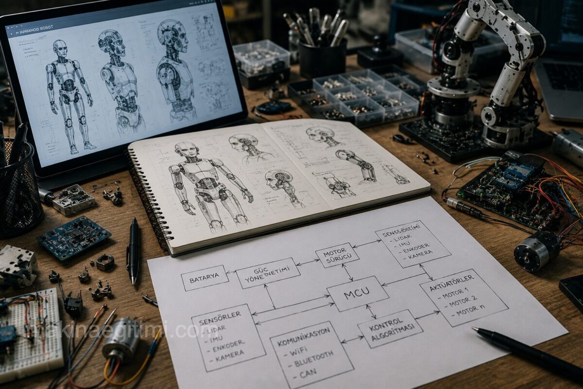
A poorly planned robot project can lead to serious mechanical mismatches and budget overruns down the line. In this first part of the series, we look at the planning and design steps that should be followed when starting a robot project.
Step 1: Clarify the Mission Definition
The first question to ask before starting a robot design is: what task will this robot perform? The clearer the mission definition, the easier all subsequent design decisions become. For example, a line-following robot and an obstacle-detecting-and-avoiding robot have entirely different sensor and software requirements.
When defining the mission, the following questions should be answered:
- In what environment will the robot operate (flat ground, rough terrain, underwater)?
- How fast should the robot move?
- How much weight will the robot carry, or what should its own weight be?
The answers to these questions form the foundation of the robot’s technical specifications.
Step 2: Determine the Robot Type
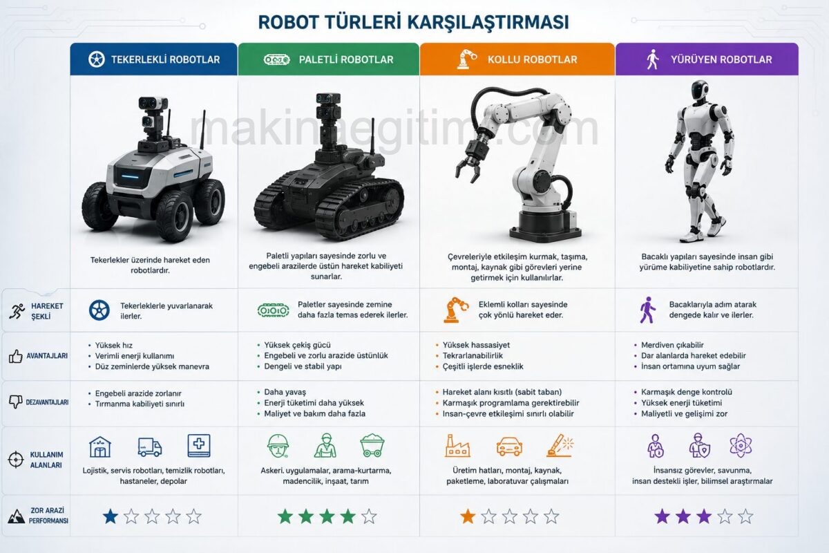
Once the mission definition is clear, the robot type that will best accomplish that task should be chosen. The most common robot types for beginners are:
- Wheeled robots are the simplest and lowest-cost solution for movement on flat and moderately rough terrain; they can easily be built with two- or four-wheel configurations.
- Tracked robots provide better traction on rough terrain but come with higher mechanical complexity and energy consumption. Robot arms (manipulators) are preferred for tasks such as grasping objects or assembly at a fixed point.
- Walking robots are the most complex category in terms of mechanics and control, and are generally suited to advanced projects.
Beginners are advised to start their first project with a wheeled platform, since this type of robot has the lowest learning curve in terms of both mechanics and software.
Step 3: Mechanical Design and Material Selection
The chassis design that forms the robot’s physical structure requires a material choice that balances durability and weight. Acrylic (plexiglass) sheets are frequently chosen for beginner-level projects because they are easy to cut and low-cost, though they are brittle against impacts.
Aluminum profiles and sheets offer higher durability and are commonly used in intermediate-level projects. PLA or ABS plastic parts produced with a 3D printer make it possible to manufacture custom components with complex geometries at low cost.
When designing the chassis, sufficient space should be left for the placement of motors, the battery, and electronic boards, and care must be taken to position the center of gravity so that it doesn’t negatively affect the robot’s stability.
Step 4: Power Budget and Weight Calculation
A frequently skipped but critical step in robot design is working out the power budget. In this stage, the current drawn by the motors and the power consumption of the sensors and microcontroller are added together to calculate the required battery capacity.
For example, if two DC motors each draw an average of 500 milliamps and the electronics board consumes 200 milliamps, the total current consumption comes to roughly 1.2 amps; this figure directly affects the capacity of battery you choose and the expected runtime.
Weight calculation is also decisive for motor selection, because a motor’s torque rating must be sufficient to move the robot’s total weight given the wheel radius.
Step 5: Visualize the System Architecture with a Block Diagram
Once the mechanical and power decisions are finalized, it’s recommended to create a block diagram showing all of the robot’s subsystems. This diagram shows the connections between the microcontroller, sensors, motor drivers, battery, and communication modules using simple boxes and arrows. Because a block diagram lets you see the whole system before a single circuit board is soldered, it helps catch missing or conflicting components at an early stage.

Step 6: Parts List and Budget Planning
Once the design is finalized, a parts list (bill of materials) covering all required components should be prepared. This list typically includes the microcontroller board, motor and motor driver, sensors, battery, chassis material, and fasteners (screws, nuts, cables).
By noting the lead time and cost for each component, the total budget can be estimated in advance. The recommended approach for beginners is to work with a minimum number of components on the first project and gradually increase sensor and functional variety as experience grows.
Common Planning Mistakes
One of the most common mistakes made by beginner robot designers is buying parts before clarifying the mission definition; this typically leads to acquiring mismatched or unnecessary components.
Another common mistake is choosing a motor without accounting for the power budget; this can cause the robot to move with insufficient power or drain the battery much faster than expected. Finally, failing to leave room for expansion in the mechanical design can make it difficult to add new sensors or modules later on.
Conclusion
The planning stage of robot design is critically important to the healthy progress of the rest of the project. Clarifying the mission definition, choosing the right robot type, working out the mechanical and power calculations, visualizing the system architecture, and budget planning are all fundamental steps that experienced engineers follow on every project. In the next part of the series, we’ll cover the hardware selection and circuit design that follow this planning stage.
Frequently Asked Questions
You should start robot design by writing a mission definition that clarifies what task it will perform. This definition shapes all subsequent decisions, such as robot type, sensor needs, and mechanical structure.
Wheeled robot platforms are recommended for beginners because they’re simpler to build mechanically and control in software compared to other robot types (tracked, armed, walking).
Acrylic sheets are commonly used for beginner-level projects, aluminum profile and sheet for intermediate-level projects, and 3D-printed PLA or ABS plastic for custom-geometry parts.
The power budget calculates the total current consumption of the motors and electronic components, allowing you to select the correct battery capacity and estimate the robot’s expected runtime.
A block diagram visualizes the connections between all of a robot’s subsystems (microcontroller, sensors, motor drivers, battery), helping to catch missing or conflicting components before the circuit is built.
Related Posts
 Robot Kinematics and Dynamics: Foundations of Mathematical Modeling
  Robot Films Worth Watching: The Best Recent Robot-Themed Movies
  How to Build a Robot? Part 4: Testing, Calibration, and Moving to Autonomy
  How to Build a Robot? Part 2: Hardware Selection and Circuit Design
  Robot Perception Through Image Processing and Computer Vision
  Drone (UAV) Technology: Structure, Applications, and Current Developments
  The History and Evolution of Robotics: From Ancient Automata to AI-Powered Robots
  Fundamental Components of Robot Technology: Sensors, Actuators, and Control Systems