
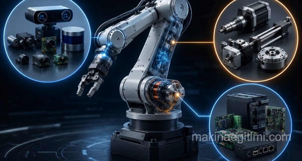
What are robot components? is one of the first questions anyone starting out in robotics engineering encounters. An industrial robot arm, an unmanned aerial vehicle, and a humanoid robot may look very different on the surface, but they’re fundamentally built from the same three layers:
Sensors that perceive the environment,
Actuators that produce physical motion, and
Control systems that manage the flow of information between the two.
In this article, we take a technical look at these three fundamental components of robotic technology.
Sensors: The Robot’s Perception Layer
Robotic sensor types fall into two main categories based on what they measure: proprioceptive and exteroceptive sensors.
Proprioceptive sensors measure the robot’s own internal state. Encoders track joint angles and rotational speeds, inertial measurement units (IMUs) — made up of accelerometers and gyroscopes — determine the robot’s position and orientation, and torque sensors measure the force applied to the joints.
Exteroceptive sensors enable the robot to perceive its external environment. Cameras process visual data for object recognition and navigation. LIDAR (Light Detection and Ranging) systems emit laser beams to measure distances to surrounding objects with millimeter precision, and are widely used for mapping in autonomous vehicles and mobile robots.
Ultrasonic sensors measure distance using sound waves, while touch and force sensors provide feedback at the moment of contact with objects during robotic manipulation tasks. Artificial tactile skins developed in recent years enable humanoid robots to grasp objects with a level of precision approaching that of the human hand.

Actuators: The Robot’s Motion Layer
The answer to what is an actuator is simple: actuators are components that convert electrical or digital signals coming from the control system into physical motion. Three basic actuator types are used in robotic technology.
Electric motors are the most common actuator type. DC motors offer simple, low-cost solutions, while servo motors are preferred in applications requiring precise position control. Step motors, on the other hand, provide precise positioning in open-loop systems by rotating in defined angular steps.
Hydraulic actuators are used in heavy industrial robots and construction machinery that require high force and torque, but their maintenance costs are higher since they require hydraulic fluid systems. Pneumatic actuators, on the other hand, run on compressed air, offer fast response times, and are generally preferred in industrial applications requiring simple open-close movements.
Recently developed series elastic actuators increase resistance to impacts by placing a flexible element between the motor and the load, and are widely used in collaborative robots (cobots) that require safe interaction with humans.
In humanoid robots, compact electric actuators with high power density are preferred to provide a range of motion similar to that of human muscle.
Control Systems: The Robot’s Decision Layer
How does a robot control system work is perhaps the most complex technical area in robotics. Control systems process data coming from sensors and generate commands for actuators about what movement to perform, when, and how. This process is generally carried out using either an open-loop or closed-loop control approach.
In open-loop control, the system executes a predefined sequence of commands without receiving feedback. In closed-loop control, sensor data is continuously fed back to the controller, and the system attempts to reduce the difference between the target state and the actual state.
The most common implementation of closed-loop control is the PID (Proportional-Integral-Derivative) controller. The PID controller determines the command signal to be sent to the actuator by calculating three separate terms based on the magnitude, accumulation, and rate of change of the error value. More complex robotic systems use state-space control, model predictive control (MPC), and reinforcement-learning-based control algorithms.
On the software side, ROS (Robot Operating System) is currently used as the standard development framework in the majority of academic and industrial robotics projects. ROS makes it possible to manage tasks such as sensor data processing, motion planning, and hardware control through modular software packages (nodes). Real-time operating systems, especially in safety-critical applications, guarantee that the control loop runs without interruption at defined time intervals.

Integration of the Components: The Sense-Plan-Act Loop
In modern robotic systems, these three components operate within a continuous loop called “sense-plan-act.” Sensors collect data about the environment and the robot’s own state, the control system processes this data to create a motion plan, and actuators convert this plan into physical motion.
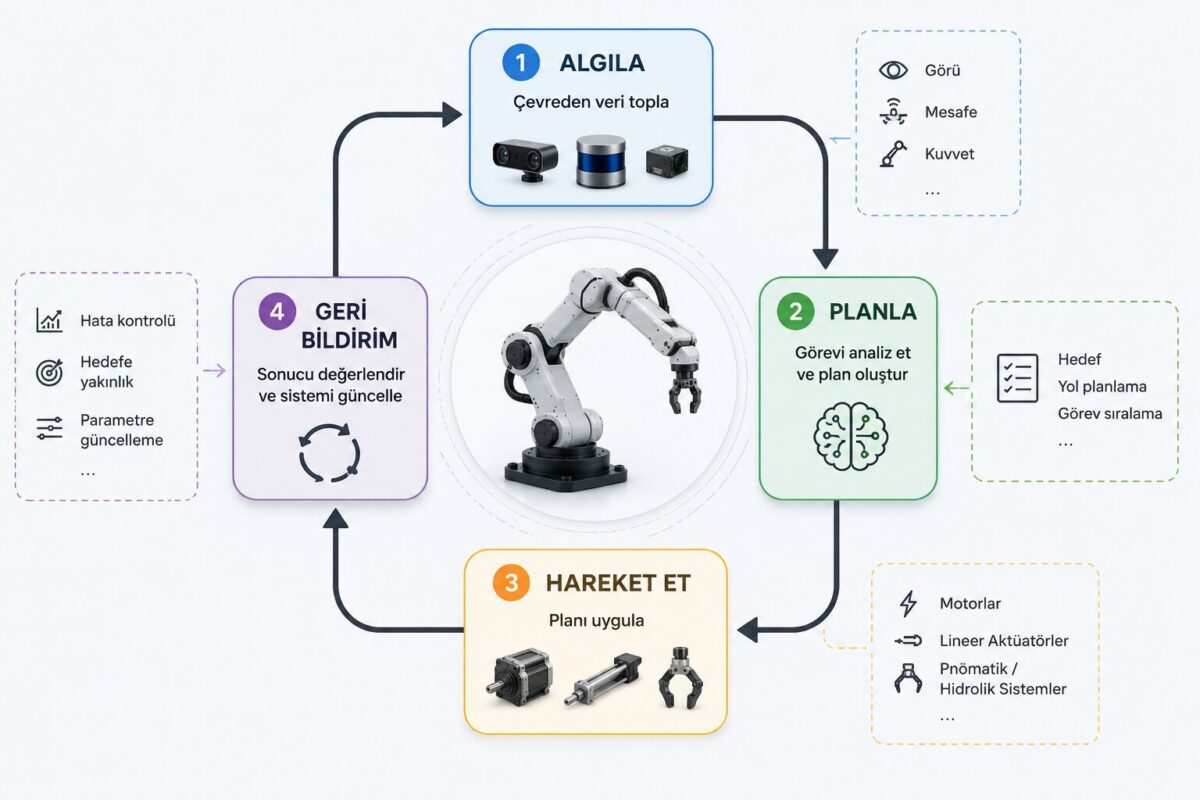
In modern AI-powered robots, this loop has also incorporated perceptual inferences produced by deep learning models and learned motion policies. This allows robots to make relatively flexible decisions even in scenarios that were not predefined.
Conclusion
Sensors, actuators, and control systems — the fundamental components of robot technology — are not independent parts working in isolation, but an integrated whole in continuous data exchange. Technological advances in each of these components directly affect how precise, safe, and autonomous robots become. In the next article, we’ll look at the concrete applications in which these components are used in industrial robots.
Frequently Asked Questions
The basic components of a robot are sensors, actuators, and the control system. Sensors handle perception, actuators produce motion, and the control system manages the decision-making process between the two.
Proprioceptive sensors measure the robot’s own internal state (joint angle, speed, acceleration), while exteroceptive sensors perceive the robot’s external environment (distance, image, sound).
The most common actuator types in robotic technology are electric motors (DC, servo, step motors), hydraulic actuators, and pneumatic actuators. Each is chosen according to different force, speed, and precision requirements.
A PID controller is a closed-loop control method that determines the command sent to the actuator by calculating the difference between the target value and the actual value through proportional, integral, and derivative terms.
ROS is a widely used robot software development framework that makes it possible to manage tasks such as sensor data processing, motion planning, and hardware control in robotics projects through modular software components.
Related Posts
 How to Build a Robot? Part 4: Testing, Calibration, and Moving to Autonomy
  Drone (UAV) Technology: Structure, Applications, and Current Developments
  How to Build a Robot? Part 3: Software and Control Algorithms
  Robot Perception Through Image Processing and Computer Vision
  Industrial Robot Applications: Sector Use Cases and Technical Features
  The History and Evolution of Robotics: From Ancient Automata to AI-Powered Robots
  Robotic Technology in Türkiye: Domestic Ventures and Projects
  2026 Developments in Robotics Technology: The Age of Physical AI