

Technical drawing / CAD-CAM / SolidWorks training material — dimensioned isometric drawing examples.
Topic content: three-dimensional (3D) isometric drawing examples that our technical drawing and vocational drawing teachers can use in exams — mostly for computer-aided drawing programs such as AutoCAD, CAD-CAM, and SolidWorks.
Students and those just starting to learn AutoCAD can also use them for practice.
3D isometric drawing examples – 1
The parts shown are of varying difficulty and all have been fully dimensioned. They’re ideal for practicing three-view extraction, especially for teaching hidden lines.

A very simple exercise, well suited for the introductory part of a three-view extraction lesson. (above)

The second part is a bit more challenging. There’s a detail to watch for when drawing the left side view. (above)


An example part with just a single hidden line in the left side view (above)

A part with hidden dashed lines in the top and left side views, and quite a few stepped details.

The same part, color-coded by viewing direction.

An example part that requires care when drawing the left side and top views (above)

Color-coded view of the part.

A part resembling a V-block. There are hidden sections in the top and left side view drawings (above)

Dashed lines appear in the top and left side views. One of the surfaces has to be drawn in both the top and front views. This surface is shaded with a mix of yellow and gray. (above)

Color-coded view of the part.

Like the previous part, one of the surfaces here also has to be drawn in both views (top view and left side view). This surface is marked with a black-to-gray gradient.

Color-coded view of the part. Different colors were assigned by viewing direction for the three-view extraction exercise.

An example part resembling a blind plug. Suitable for hexagon (polygon) drawing practice.

A view of the part reminiscent of its solid model.

An interesting example part containing a detail visible in all three views. (above right)

Students need to be careful when extracting the left side view of this part, because the 15 mm-thick protrusion doesn’t appear in the left side view.

A pretty ideal example for teaching hidden sections (dashed lines). (above right)

Another isometric example that has dashed lines (hidden sections) to watch for in the front and left side views.

You can download the part’s SolidWorks solid model file FROM HERE >> A15.SLDPRT

An isometric with a dovetail slot.

A part drawing well suited for introductory three-view extraction exercises.
By popular request, we combined all the drawings shown above one by one into a single PDF file. You can download it from the link below.
Download the isometric drawings PDF file
Related Posts
 Dimensioned Isometric Drawing Examples – Part 2
 Showing Specially Treated Surfaces in a Drawing
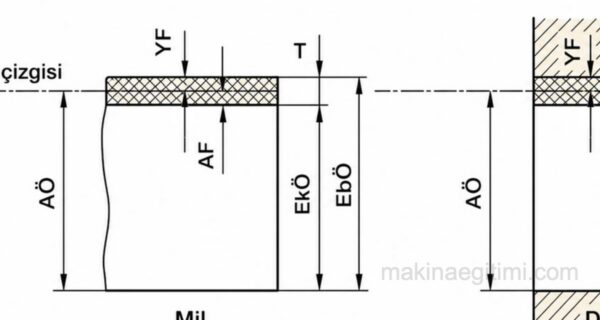 Tolerance Terms and Their Meanings in Mechanical Engineering
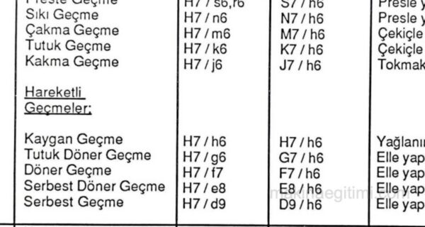 Choosing Tolerance Zones and Fits
 International Projection Standards ISO-E and ISO-A
 Geometric Drawings 2 – Dividing Circles
 Form and Position Tolerances in Technical Drawing
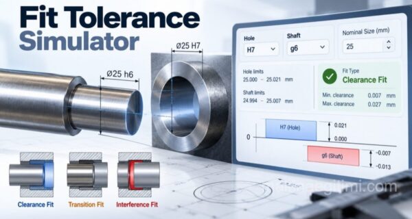 Fit Tolerance Simulator