
In our technical drawing lessons section, we’ve dedicated this article to the topic of auxiliary views in technical drawing. We’ll cover topics such as what an auxiliary view is, why an auxiliary view is drawn, how an auxiliary view is drawn, and what an auxiliary projection plane is. We’ll provide auxiliary view drawing examples.
Auxiliary View
Why Is an Auxiliary View Drawn?
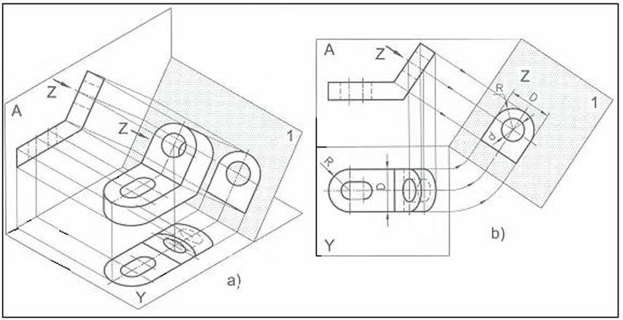
In parallel orthographic projection methods, only surfaces and lines parallel to the projection planes can be drawn in their true shape and size. Since many objects consist of regular surfaces perpendicular to each other, it’s possible to think of these objects, while drawing, so that their surfaces are parallel to the projection planes. However, for objects that aren’t regular and have surfaces facing various directions, this convenience isn’t available, and most of the surfaces can’t be shown in their true shape and size. Such a situation creates difficulty in the drawing, in understanding the drawing, and in dimensioning it — for example, the hole on the part given in the figure below will appear as an ellipse in the top and left-side views.

What Is an Auxiliary Projection Plane?
The figure shows how these ellipses would be drawn point by point. Although it’s possible to draw the ellipses approximately with a simpler method, drawing an ellipse is more difficult and time-consuming than drawing a circle with a compass. Dimensioning this hole is also only possible by taking a partial section in the front view, since dimensions can’t be given from hidden (dashed) lines. In cases like this, in addition to the main projection planes, auxiliary projection planes are used.
These planes are generally taken parallel to the inclined surfaces of the object. This way, the orthographic projections of the inclined surfaces onto these planes are obtained in their true size. If an auxiliary projection plane parallel to the inclined surface of the part above is used, and this plane is then rotated into the plane of the paper, the situation shown in the figure below is obtained.
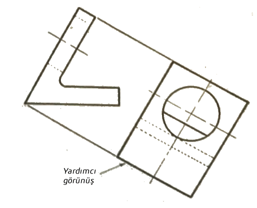
This drawing, consisting of the front view and the auxiliary view, fully describes the part without needing a top or left-side view. Since the hole now appears as a circle, both the drawing and the dimensioning can be done more simply.
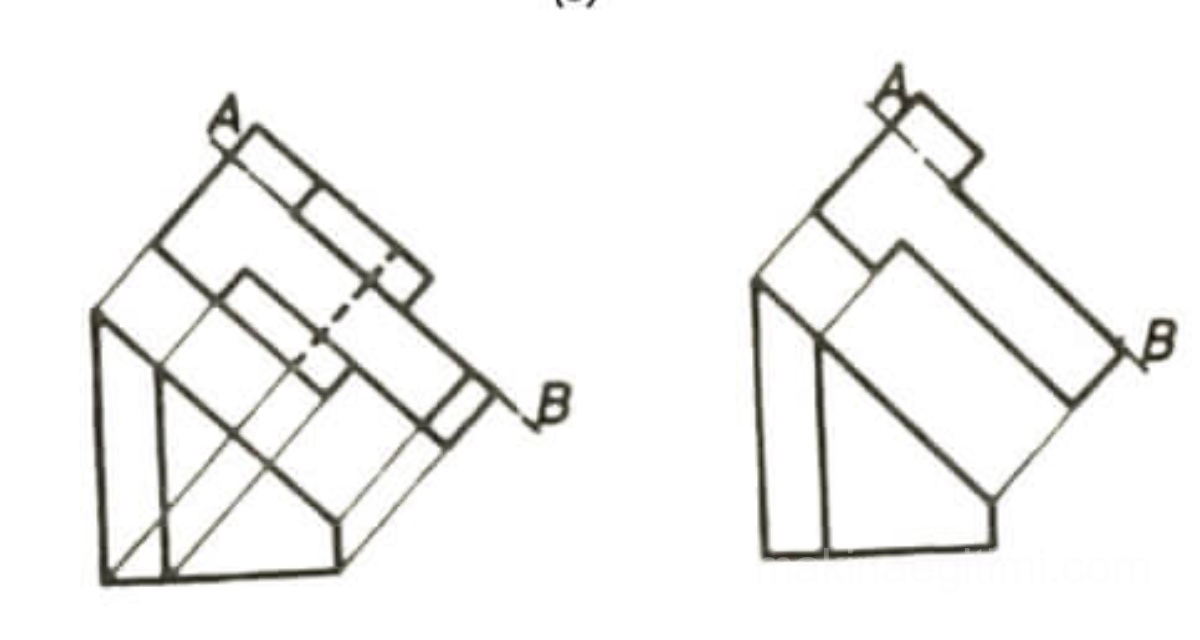
The reason auxiliary projection planes are used is mainly to reveal the shape of inclined surfaces, so often, not the projection of the entire shape, but only the projection of the inclined surfaces, is drawn on them. The full projection onto the auxiliary plane of the object seen in Figure 3-a is shown in Figure 3-b. Instead, showing only the inclined surface, as in Figure 3-c, makes both the drawing and understanding it easier.
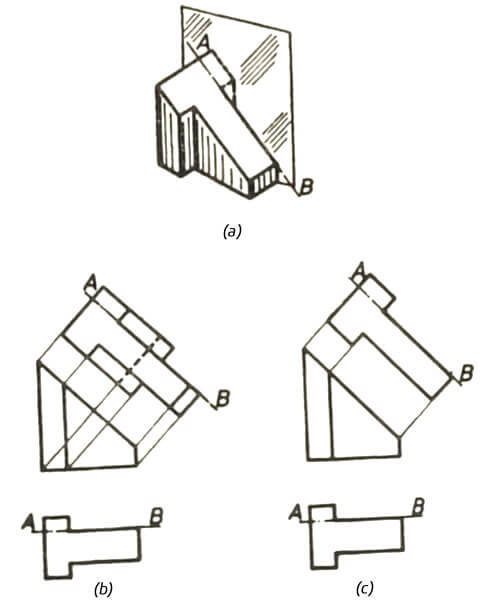


To transfer distances when drawing the auxiliary view, a reference line is chosen on or at the edge of the surface, and the view is thought of as though it’s being rotated around this line into the plane of the paper. Line A-B in Figure 3 is a line chosen for this purpose. Figures 4 and 5 show two examples of auxiliary views in which only the inclined surface is shown.
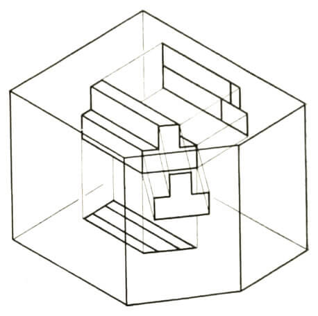

When an auxiliary view is used, the inclined-surface portions of the object’s main views, which are difficult to draw, are sometimes omitted from those main views, and the missing part is completed with the auxiliary view. In the example in Figure 6, the top view is drawn partially, and the inclined surfaces are shown with the auxiliary view.
In such cases, the drawn portions of the view are bounded by a freehand line.

How Is an Auxiliary View Drawn?
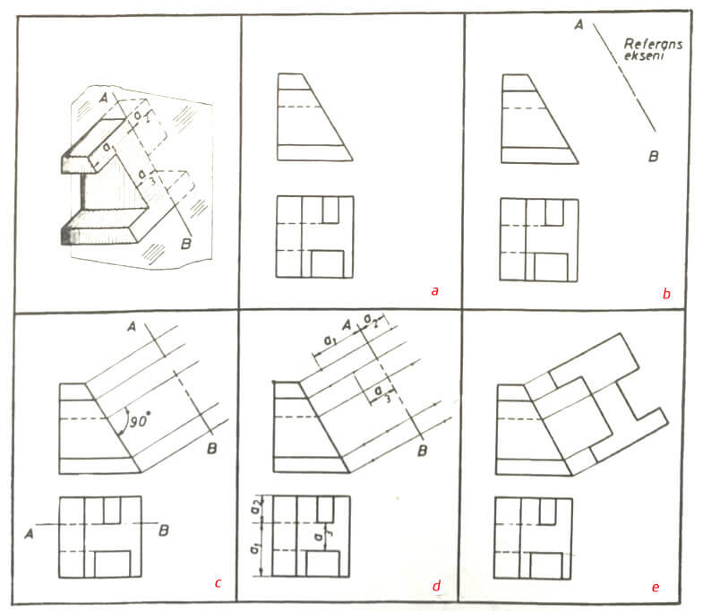
Auxiliary views are drawn according to the rules of parallel orthographic projection, making use of the main views. Figure 7 (below) shows the drawing method and sequence for the example given. According to this sequence:
a) First, the main views are drawn.
b) Since the auxiliary projection plane parallel to the inclined surface is rotated into the plane of the paper, the reference axis (axis of rotation) A-B is established.
c) Auxiliary lines perpendicular to the reference axis are drawn from the main view to carry the points across.
d) The distances of the points from the reference axis are taken from the main view and transferred onto the corresponding auxiliary lines on the auxiliary view.
e) Once all the points are found, they’re connected and the drawing is completed.
Related Posts
 How to Draw an Ellipse? Ellipse Construction.
  Surface Roughness in Technical Drawing
  Geometric Drawings 3 – Drawing Polygons
  Fit Tolerances and Tolerance Pairs – Lesson 3
  International Projection Standards ISO-E and ISO-A
  Types of Sectioning in Technical Drawing? Sectioning Methods
  Introduction to Surface Finish Symbols
  Form and Position Tolerances in Technical Drawing