

Our technical drawing lessons continue with form and position tolerances. In this section we’ll cover form and position tolerances, their symbols, and how they’re shown on a technical drawing.
Giving only the dimensions of machine parts in a technical drawing isn’t always enough to ensure the part is manufactured correctly. Two parts with the exact same dimensions may still fail to mate properly because of geometric errors.
For example, consider two shafts with a diameter of Ø40 mm. Even though their dimensions are identical, one shaft could be bent, a hole’s center could be offset, or a surface might not be perfectly perpendicular to the reference surface. Errors like these cause assembly problems, vibration, wear, and quality issues.
This is why form and position tolerances (Geometric Dimensioning and Tolerancing — GD&T) are used in technical drawings. These tolerances don’t just define a part’s size — they define how much its form, orientation, and location are allowed to deviate. The ISO 1101 standard sets the international rules for how these tolerances are represented.

A size tolerance only limits a part’s dimension. For example, the note Ø25 ±0.05 mm only requires the diameter to be between 24.95 and 25.05 mm. But it doesn’t guarantee that the hole’s center hasn’t shifted, that the axis isn’t tilted, that the surface is flat, or that the hole was machined perfectly perpendicular. All of these are controlled through geometric tolerances.
That’s why modern technical drawings use size tolerances together with geometric tolerances.
Why Are Form and Position Tolerances Used?
Even on today’s CNC machines, perfectly flawless production isn’t possible. Cutting tools wear. Machines heat up. Clamping errors can occur. Material stresses can shift. This is why every part is given an acceptable margin of error.
The main purposes of form and position tolerances are:
- Ensuring parts assemble together smoothly
- Reducing manufacturing cost
- Avoiding unnecessarily precise machining
- Making quality control easier
- Establishing a shared technical language between manufacturer and customer

Correctly specified geometric tolerances both reduce production time and improve part quality.
How Are Form and Position Tolerances Measured?
Geometric tolerances are checked using various measuring equipment. The most commonly used instruments are:
Calipers, micrometers, dial indicators, gauges, height gauges, CMMs (Coordinate Measuring Machines), optical measurement systems
In the automotive, aerospace, and defense industries — where high precision is required — CMM devices are widely preferred.
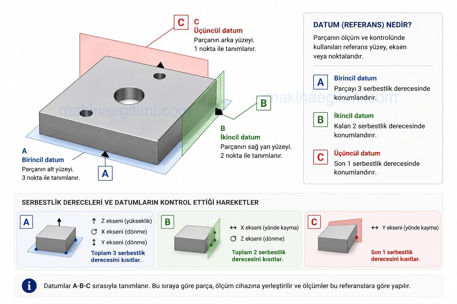
What Is a Datum?
To measure a part’s accuracy, a reference must first be chosen.
This reference — a datum — can be a surface, an axis, a hole, or a center plane.
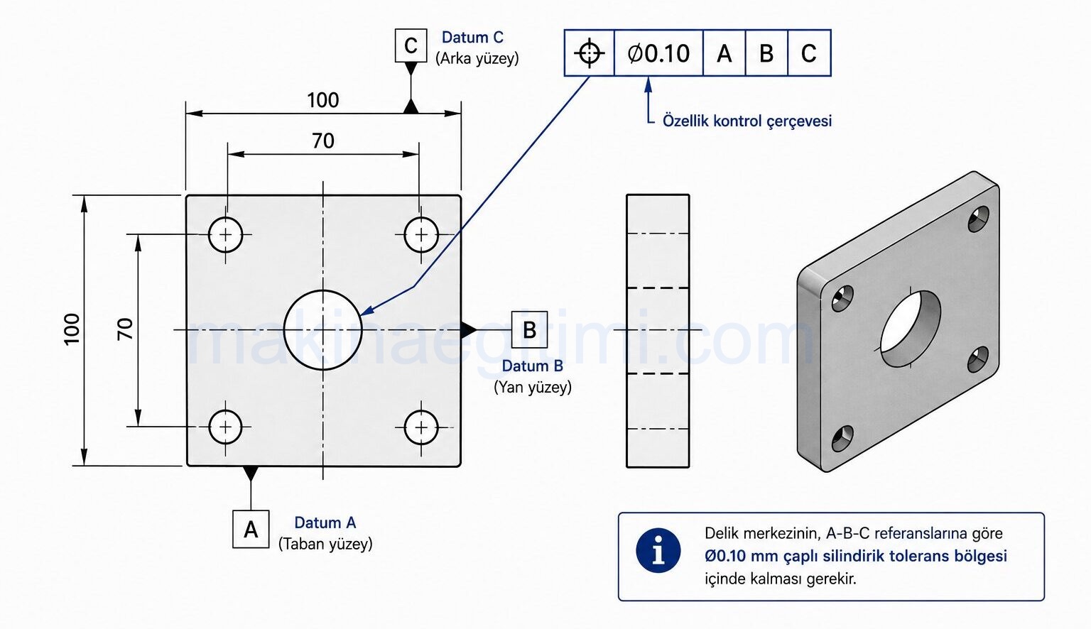
In technical drawings, datums are usually labeled with the letters A, B, and C. For example, when measuring the location of a hole, the base surface might be taken as datum A, the side surface as datum B, and the front surface as datum C. This way, all measurements are made relative to the same starting point.
How Do You Read a Tolerance Frame?
Geometric tolerances are shown using a rectangular box called a feature control frame. The frame generally contains the following information:
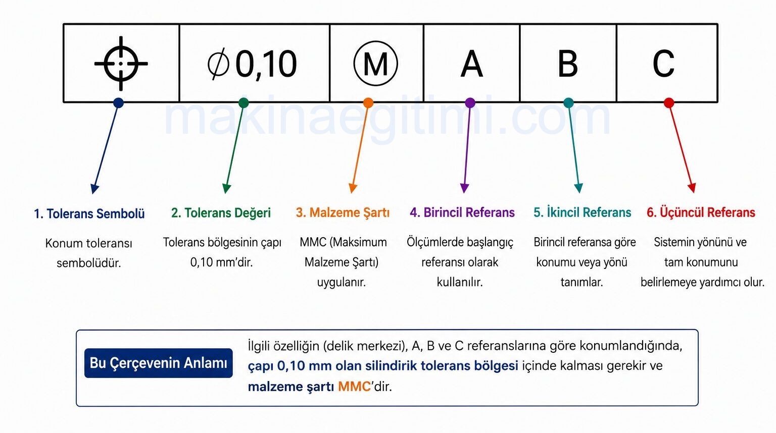
The tolerance symbol, the tolerance value, a diameter symbol if applicable, the material condition (MMC/LMC), and the datum references
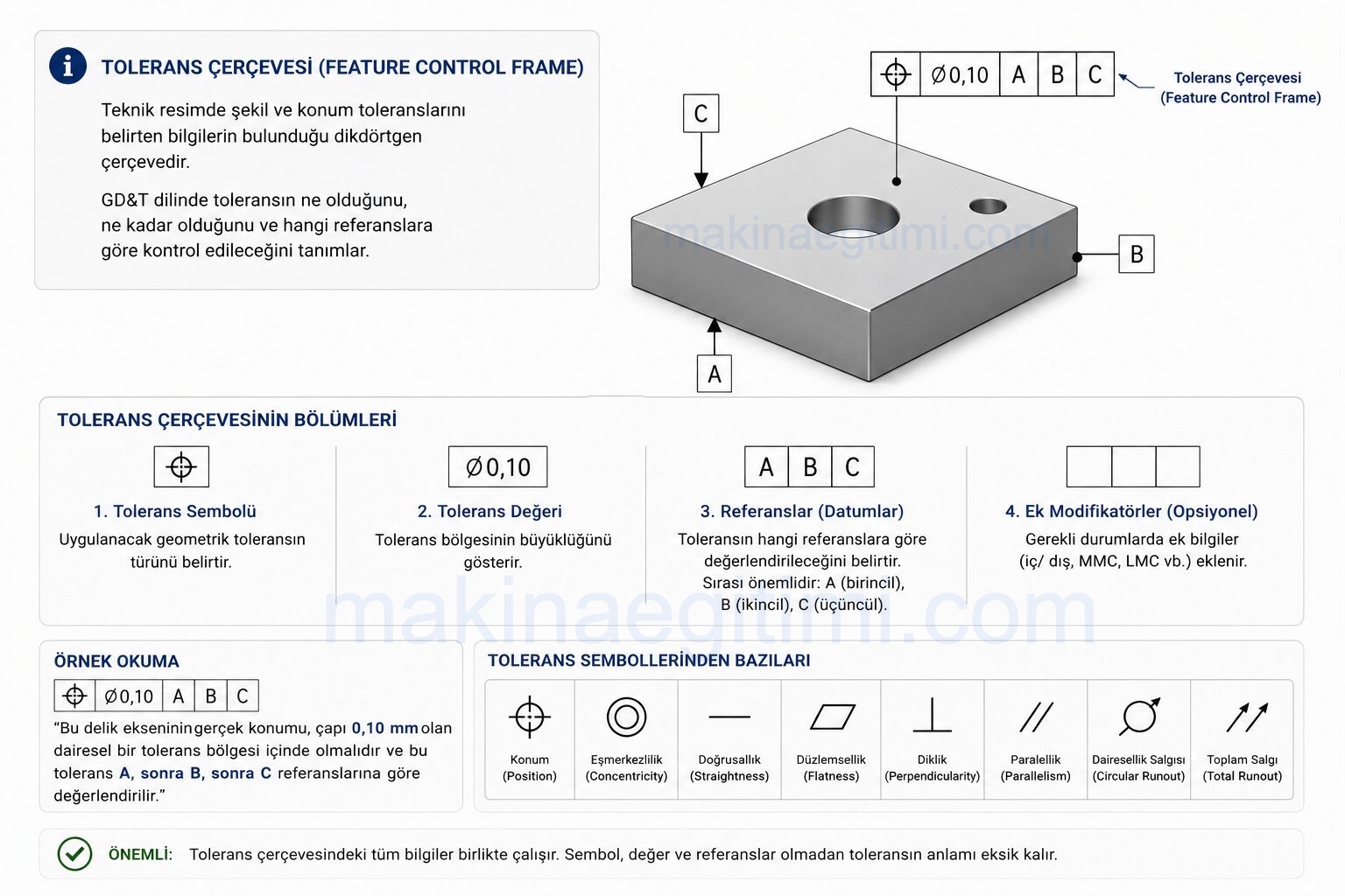
For example, ⌖ Ø0.10 A B C means: “The center of the hole must lie within a cylindrical tolerance zone of 0.10 mm diameter, relative to datums A-B-C.”
Classification of Form and Position Tolerances
Under the ISO 1101 standard, geometric tolerances are divided into five main groups.
Form Tolerances
Straightness
A straightness tolerance is a form tolerance that requires a surface or axis running along a line to stay within a defined tolerance zone. It limits any curvature, bending, or waviness that could occur in areas of the part that should be straight.
Straightness only controls the accuracy of the form. It doesn’t evaluate the part’s location or orientation relative to another surface. This is why it’s classified among the form tolerances that don’t require a datum.
In technical drawings, the straightness symbol is shown as a horizontal line (―) and is given inside the feature control frame together with the tolerance value.
What Is a Straightness Tolerance For?
Even if a part’s dimension is correct, its axis or surface can still be curved. Even small amounts of curvature — especially on long shafts, rails, and guide surfaces — can seriously affect a machine’s performance.
Thanks to a straightness tolerance;
- Axial accuracy is maintained on shafts.
- Smooth motion is ensured on slide and rail systems.
- Wear on linear bearings is reduced.
- Vibration and noise levels are lowered.
- Binding and strain during assembly are prevented.
- The service life of moving mechanisms is extended.
Straightness is especially important in precision machine manufacturing, on CNC machines, and in automation systems.

How Is a Straightness Tolerance Shown?
In technical drawings, a straightness tolerance is specified inside a feature control frame.
Where Is a Straightness Tolerance Used?
A straightness tolerance is used on nearly every machine component where linear motion matters. Common applications include:
Shafts, linear slides, CNC machine rails, hydraulic and pneumatic cylinder rods, lead screws (trapezoidal and ball screws), guide pins, press columns, machine body reference surfaces, gauge blocks, precision linear slide systems

Even a small amount of curvature in these parts can disrupt motion accuracy, increase friction, and cause premature wear.
A Real Manufacturing Example
Let’s look at a hydraulic cylinder rod as an example.
Say the rod’s diameter is specified in the technical drawing as Ø40 h6. Even if the diameter tolerance is met, the rod may have bent slightly during manufacturing. A rod like this will cause friction as it passes through the bushings inside the cylinder, and can lead to the seals wearing out quickly.
This is why the technical drawing doesn’t just specify a diameter tolerance — a separate straightness tolerance of 0.02 mm is also defined for the rod’s axis. This keeps the entire axis of the rod within the specified accuracy limits, so the cylinder operates smoothly.
Similarly, straightness tolerance on the linear slides of CNC machines is critical for allowing the tool to move precisely over the workpiece.
How Is a Straightness Tolerance Measured?
A straightness tolerance can be checked with different measurement methods depending on the part’s precision requirements. The most common methods are:
- Dial indicator and granite surface plate
- Axis check with a dial indicator on a V-block
- CMM (Coordinate Measuring Machine)
- Laser alignment measurement systems
- Optical measuring instruments
In the aerospace, automotive, and tool & die industries — where high precision is required — CMM devices are one of the most reliable measurement methods.
Flatness Tolerance
A flatness tolerance is a form tolerance that specifies how flat a surface needs to be. It ensures that every point on the surface stays between two parallel planes spaced apart by the specified tolerance value.
While straightness controls deviation along a single line, flatness controls the flatness of an entire surface. Because of this, it doesn’t require a datum and is classified among the form tolerances.
A flatness tolerance is especially used on the following surfaces:
- Assembly surfaces of machine housings
- Flange surfaces
- Mold and fixture bases
- Bearing seating surfaces
- Precision clamping plates
- Gasket contact surfaces

Correctly specifying flatness tolerance prevents assembly errors, sealing problems, and uneven load distribution across a surface. In hydraulic and pneumatic systems especially, having sufficiently flat gasket surfaces is critical for reliable system operation.
Circularity Tolerance
A circularity tolerance is a form tolerance that specifies how close any cross-section of a cylindrical or conical part needs to be to a perfect circle. It ensures that every circular cross-section of the part stays within the specified tolerance zone.
Circularity only controls the geometric accuracy of a single cross-section. It doesn’t evaluate the part’s axis, orientation, or location relative to another surface. This is why it’s classified among the form tolerances that don’t require a datum.

A circularity tolerance is used especially on the following parts:
- Bearing seats
- Shafts
- Bushings
- Pistons
- Hydraulic and pneumatic cylinders
- Precision-machined holes
A correctly specified circularity tolerance reduces vibration during rotation, extends bearing life, lowers friction, and helps parts operate more precisely. Circularity is especially important on high-speed rotating machine components.
Cylindricity Tolerance
A cylindricity tolerance is a form tolerance that specifies how close the entire outer or inner surface of a cylindrical part needs to be to a perfect cylinder. This tolerance evaluates the entire cylinder — controlling the geometric accuracy of the whole cylindrical surface, not just a single cross-section.
Cylindricity evaluates straightness, circularity, and axis accuracy together under a single tolerance. Because of this, it doesn’t require a datum and is classified among the form tolerances.

Cylindricity tolerance is used especially on shafts, hydraulic and pneumatic cylinders, bearing seats, bushings, precision-machined holes, and shaft-hub connections.
A correctly specified cylindricity tolerance ensures parts rotate smoothly, seat properly in bearings, reduces friction, and improves sealing performance. It’s especially important on precision rotating machine components and hydraulic systems.
Orientation Tolerances
Parallelism Tolerance
A parallelism tolerance is an orientation tolerance that defines how parallel a surface, axis, or center plane must be to a specified datum surface or axis. Unlike form tolerances, it’s always evaluated relative to a datum feature.
A parallelism tolerance maintains the parallelism between two surfaces or two axes, preventing problems like binding, uneven load distribution, and premature wear that can occur during assembly.
Parallelism tolerance is used especially on the following parts:
- Linear slide and rail systems
- Assembly surfaces of machine housings
- Bearing seats
- Vises and clamping fixtures
- Flange surfaces
- Reference surfaces on CNC machines

A correctly specified parallelism tolerance ensures moving parts operate smoothly, load is distributed evenly across the surface, and assembly precision is maintained. It’s widely used in precision machine manufacturing, tool & die making, and the automotive industry.
Perpendicularity Tolerance
A perpendicularity tolerance is an orientation tolerance that ensures a surface, axis, or center plane is positioned at an exact 90° angle to a specified datum surface or axis. This tolerance controls how perpendicular the part is relative to its datum feature, and it always requires a datum.
A perpendicularity tolerance ensures surfaces and holes are at the correct angle during assembly. This prevents alignment errors, binding, and uneven load distribution that could otherwise occur between parts.
Perpendicularity tolerance is used especially on: flange and connection surfaces, hole axes, machine housings, vises and clamping fixtures, CNC-machined parts, mold and fixture components

A correctly specified perpendicularity tolerance improves assembly precision, ensures parts align correctly, and reduces wear and vibration in moving systems. It’s widely used in precision machine manufacturing, automotive, aerospace, and tool & die industries.
Angularity Tolerance
An angularity tolerance is an orientation tolerance that positions a surface, axis, or center plane at a specific angle other than 90° relative to a specified datum surface or axis. This tolerance controls how much the feature is allowed to deviate from the angle specified in the drawing, and it always requires a datum.
While perpendicularity tolerance only applies to 90°, angularity tolerance can be applied to any angle, such as 30°, 45°, or 60°.
Angularity tolerance is used especially on: tapered surfaces, angled assembly surfaces, mold and fixture components, keyways, angled surfaces on machine housings, aerospace and automotive parts

A correctly specified angularity tolerance ensures parts are manufactured at the designed angle, improves assembly precision, and helps loads transfer in the correct direction. It’s widely used on precision machine components that have angled contact surfaces.
Location Tolerances
Position Tolerance
This is the most commonly used geometric tolerance. It ensures holes, pins, and fasteners are located in the correct position.

It’s especially common on flanges, molds, and connection plates produced on CNC machining centers.
Concentricity Tolerance
This controls the accuracy of cylindrical parts that need to share the same axis. It’s used on motor shafts, bearing seats, and pulleys.

Symmetry Tolerance
A symmetry tolerance is a location tolerance that ensures a surface, axis, or center plane is symmetrically positioned relative to a specified datum center plane. This tolerance controls whether two surfaces or two features are equidistant from the datum plane, and it always requires a datum.
Symmetry tolerance is used especially on: keyways, slots and grooves, fork-shaped parts, machine housings, mold components, symmetric assembly surfaces

A correctly specified symmetry tolerance ensures balanced load distribution, correct alignment of parts, and preserved assembly precision. It’s used especially on machine components that need to be positioned equally relative to a center plane.
Runout Tolerances
Circular Runout Tolerance
A circular runout tolerance is a runout tolerance that controls how evenly each circular cross-section of a rotating part turns relative to a specified datum axis. This tolerance ensures the deviation shown on a dial indicator while the part rotates doesn’t exceed the allowed value, and it always requires a datum axis.
Circular runout tolerance is used especially on: shafts, bearing seats, brake discs and drums, pulleys, gears, rotating parts mounted on a shaft

A correctly specified circular runout tolerance reduces vibration, allows quieter operation, extends bearing life, and helps rotating parts operate more precisely. It’s especially important on high-speed machine components and automotive applications.
Total Runout Tolerance
A total runout tolerance is a runout tolerance that controls how evenly the entire cylindrical surface of a rotating part turns relative to a specified datum axis. While circular runout evaluates only a single circular cross-section, total runout controls the entire surface of the part at once. Because of this, it simultaneously limits errors in circularity, straightness, and axis accuracy.
Total runout tolerance is used especially on: precision shafts, bearing seats, turbine and pump shafts, spindle systems, hydraulic cylinder rods, high-speed rotating parts
A correctly specified total runout tolerance reduces vibration, improves rotational accuracy, extends bearing life, and ensures smooth operation across the entire cylindrical surface. It’s widely used in precision spindles, CNC machines, aerospace, and automotive applications.
Common Mistakes in Form and Position Tolerancing
The most frequently encountered mistakes are:
- Specifying an unnecessarily tight tolerance
- Choosing the wrong datum surface
- Confusing size tolerance with geometric tolerance
- Specifying tolerances that can’t actually be measured
- Tolerancing surfaces that have no functional relevance
These mistakes both increase production cost and make quality control processes more difficult.
Form and Position Tolerance Symbols

Form, orientation, location, and runout tolerances are each represented by a symbol, as shown in the table above.
Helpful Notes on Form and Position Tolerances
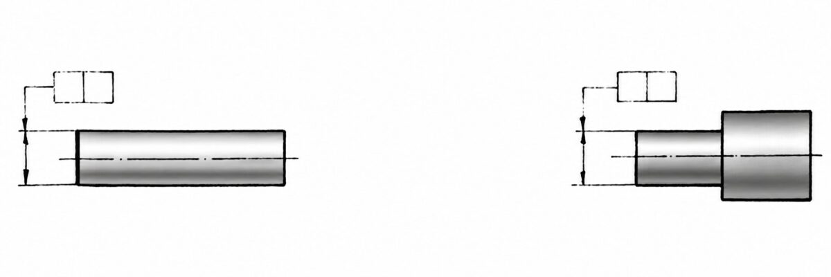
When the tolerance applies to an axis or the center plane of a dimensioned feature, it’s connected to the toleranced feature by placing it on the extension of the dimension line, in line with the leader line
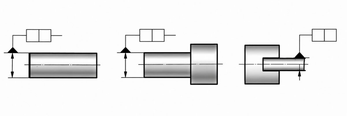
When the datum feature is the axis or center plane of a dimensioned feature, the leader line is placed in line with the extension of the dimension line. (Above)

If the tolerance applies to a specified length located anywhere, the value of that length must be appended to the end of the tolerance value, separated by a diagonal slash. The same notation is used for a surface. This means the tolerance applies to every line of the specified length, in every position and orientation. (Above)


When the maximum material condition applies to the toleranced feature, the datum feature, or both, it’s shown with the (M) symbol placed at the end of the tolerance value, the end of the datum value, or the end of both. (Above)

If a location tolerance or any form tolerance is specified for a feature, the dimensions that define its location or form should not themselves carry a tolerance. If an angularity tolerance is specified for a feature, the dimension defining the angle itself should not carry a tolerance. These nominal dimensions are enclosed in a box.
The related actual dimensions are limited only by the specified location, form, or angularity tolerances.
On drawings whose dimensions are given via a table, form and position tolerances should be shown with lowercase letters in the second compartment of the tolerance frame. The tolerance values should be given in the dimension table


Alternatively, instead of showing each tolerance notation separately on the drawing, it’s also possible to group them into a table. (Above)
Form and position tolerances are an indispensable part of modern manufacturing. In situations where size tolerances alone aren’t enough, they define a part’s true geometry and let design, manufacturing, and quality control teams speak a common language. Technical drawings prepared to the ISO 1101 standard improve assembly compatibility, reduce unnecessary manufacturing costs, and increase product reliability. Especially in the automotive, aerospace, defense, and precision machinery industries, knowledge of geometric tolerancing is now considered a core engineering competency.
Related Posts
 Technical Drawing View Extraction Examples 1
  Hatching Lines in Technical Drawing
  How to Draw an Ellipse? Ellipse Construction.
  Auxiliary Views in Technical Drawing
  Dimensioned Isometric Drawing Examples – Part 2
  Technical Drawing Paper Sizes and Folding
  Specifying the Manufacturing Method by Surface Roughness
  What Does a T-Square Do, How Is It Used?