Close Menu
  • MAKİNELER ve İMALAT
    • Tools & Equipment
    • Computer-Aided Drawing
    • CAD/CAM Education
    • CNC Machine Programming
    • Casting Technologies
    • Electrical & Electronics Technologies
    • Hydraulics & Pneumatics
    • Manufacturing Processes
    • Manufacturing Technologies
    • Occupational Safety
    • Mold & Die Design
    • Solid Modeling
    • Welding Technology
    • Machine Elements
    • Mechanical Trade Drawing
    • Materials Science
    • Automotive & Vehicle Technologies
    • Robotics Technologies
    • Health Technologies
    • Defense & Aerospace Technologies
    • Descriptive Geometry
    • Technical Drawing
    • Software & Hardware Technologies
    • Innovative Manufacturing Methods
  • TEKNOLOJİ ve YAŞAM
    • OTOMOBİLLER ve TAŞIT
      • Vehicle & Engine Knowledge
      • Safe Driving
      • Sürüş Destek Sistemleri
    • Genel Kültür
      • Movies & TV Shows
      • Görsel ve Grafik Sanat
      • Books & Literature
      • Music
      • Sports
      • History
      • History of Technology
    • GÜNDELİK YAŞAM TEKNOLOJİLERİ
    • Hobbies & Entertainment
    • Internet Technologies
    • Health
    • Mobile Technologies
Makine Eğitimi
  • Machines & Manufacturing
    Machine Elements
    Hydraulics & Pneumatics
    Technical Drawing
    Computer-Aided Design & Manufacturing
    Basic Manufacturing Processes
    Manufacturing Processes
    Industry Technologies
    Other Technical Courses
    Motion & Power Transmission
    Simple Machines
    Chains & Sprockets
    Shafts & Journals
    Gears
    Cams
    Couplings
    Belts & Pulleys
    Springs
    Bearings
    Keys
    Fastening Joining
    Retaining Rings
    Screws, Bolts & Nuts
    Cotter Pins
    Flanges
    Welding
    Rivets
    Pins & Bolts
    Washers
    Calculators
    Gear Ratio Calculator
    Spring Constant Calculator
    Belt Pulley Ratio Calculator
    Other Machine Elements
    Slides & Linear Guides
    Brakes
    Flywheels
    Clamps
    Shock Absorbers
    Gaskets & O-Rings
    Seals & Sealing Elements
    Hydraulics
    Introduction to Hydraulics & Principles
    Hydraulic Systems & Applications
    Accumulators
    Filters
    Motors
    Pumps
    Valves
    Pneumatics
    Introduction to Pneumatics & Principles
    Pneumatic Systems & Applications
    Pneumatic Circuit Components
    Valves
    Cylinders
    Silencers
    Motors
    Compressors
    Dryers
    Conditioning Units
    Common Topics & Maintenance
    Hydraulic & Pneumatic Maintenance
    Study Notes, Exams & Tests
    Technical Drawing
    Introduction to Technical Drawing
    Geometric Drawings
    Perspective & Projection
    Orthographic Views
    Dimensioning
    Sectioning
    Assembly & Detail Drawings
    Tolerances
    Surface Finish Symbols
    Mechanical Engineering Drawing
    Screws, Bolts & Nuts
    Pulley Drawings
    Gear Drawings
    Shafts & Journals
    Bearing Drawings
    Pins & Bolts
    Spring Drawings
    Welds in Technical Drawing
    Washers
    Cotter Pins
    Technical Drawing Exercises
    Mechanical Drawing Exercises
    Gear Exercises
    View Extraction Exercises
    Pulley Exercises
    Pin & Bolt Exercises
    Threaded Fastening Exercises
    Descriptive Geometry
    Computer-Aided Drawing
    AutoCAD Drawing Lessons
    Computer-Aided Drawing Exams
    Solid Modeling & Animation
    Solid Model Drawing Files
    Solid Model Assembly Examples
    Solid Model Drawing Lessons
    3D CAD Software Reviews
    Solid Modeling Exercises
    CNC Programming
    CAM
    Measurement & Inspection
    Dial Indicators
    Calipers
    Gauges
    Micrometers
    Materials Science
    Steels
    Cast Iron
    Aluminum
    Plastics
    Material Testing & Hardness Measurement
    Occupational Safety
    Workshop Safety
    Safety When Working With Electricity
    Machine Safety Rules
    Hand Operations
    Filing
    Marking
    Cutting Operations
    Reaming
    Tapping
    Threading With a Die
    Drill Bit Sharpening
    Working With Machines
    Basic Turning Operations
    Basic Milling Operations
    Shaper Machine
    Machining
    Turning
    Milling
    Grinding
    Innovative Manufacturing Methods
    EDM (Electrical Discharge Machining)
    Laser Machining
    Waterjet Machining
    3D Printing
    3D Scanners
    Welding
    Rolling
    Casting
    Mold & Die Design
    Mechanical & Hydraulic Presses
    Blanking & Piercing Dies
    Bending Dies
    Drawing Dies
    Plastic Injection Molds
    Extrusion Dies
    Compound Dies
    Progressive Dies
    Blow Molds
    Spinning Dies
    Spray Molds
    Manufacturing of Machine Parts
    Automotive & Vehicle Technologies
    Motor Vehicle Manufacturing
    Raw Material Production
    History of Technology
    Health & Medical Technologies
    Defense & Aerospace
    Robotics Technologies
    Software & Hardware Technologies
    Mechanics - Strength of Materials
    Physics Topics
  • Technology & Life
    Hobbies & Entertainment
    Sports
    Music
    Vehicle & Engine Knowledge
    Vehicle Maintenance & Repair
    Safe Driving
    Driver Assistance Systems
    History
    Movies & TV Shows
    Books & Literature
    Computers & Internet
    Computer Tips
    Software Reviews
    Hardware & Peripherals
    Practical & Safe Internet Use
    Visual & Graphic Art
    Mobile Technologies
    Travel
    Science
    Health
    First Aid Knowledge
    Everyday Technologies
Makine Eğitimi
Home»Manufacturing Processes»Indexing Operations on a Milling Machine
29 August 2026

Indexing Operations on a Milling Machine

Freze Tezgahında Bölme İşlemleri

Machine technology, manufacturing operations / indexing operations on a milling machine are used to divide cylindrical materials into equal parts. For example: gear manufacturing on a universal milling machine using traditional methods. There are two methods for this: simple indexing and differential (compound) indexing. In this article, we’ll cover topics such as simple indexing calculation and differential indexing calculation.

  • Indexing Methods Used in Milling
    • 1- Direct Indexing
    • 2- Indirect Indexing
  • Indexing Devices Used in Milling and Their Parts
    • 1- Simple Indexing Attachment
    • 2- Vertical Indexing Attachment
    • 3- Angular Indexing Attachment
    • 4- Linear Indexing Attachment
    • 5-Universal Indexing Attachment (Dividing Head)
      • Indexing with a Dividing Head
  • Rules to Follow When Performing Indexing Operations on a Milling Machine

Operations such as linear indexing, cutting grooves, cutting rack teeth, and forming polygons on a workpiece in a milling machine are defined as indexing operations. The auxiliary attachments that perform these tasks are called indexing attachments.

Circular (Radial) Indexing

Operations such as cutting grooves and holes at certain angles around the circumference of cylindrical parts, or forming polygons, are called Circular Indexing. They’re performed with devices such as a simple indexing attachment, an indexing center, or a dividing head.

Linear Indexing

Operations such as making steel rulers, manufacturing rack gears, and cutting consecutive holes or grooves are performed with surface (linear) indexing. This is done with a linear indexing device.

Indexing Methods Used in Milling

Indexing operations performed on milling machines are named according to the auxiliary device used.

1- Direct Indexing

Done with simple indexing attachments. It covers indexing operations that can be done directly, such as triangles, squares, hexagons, octagons…

2- Indirect Indexing

These are indexing operations performed using the dividing head’s index plates for divisions that cannot be done with simple indexing devices.

Indexing Devices Used in Milling and Their Parts

1- Simple Indexing Attachment

These devices allow direct indexing operations to be performed on workpieces. Indexing is performed via perforated discs or notched discs mounted at the back of the devices. The lever piece engaging with the perforated discs allows the division to be made. Simple indexing devices are mounted to the milling table with a “T”-bolt, nut, and stud. A simple indexing attachment consists of a body, a spindle, a perforated or notched disc, and a chuck or center.

2- Vertical Indexing Attachment

Has the same features as a horizontal indexing attachment. A chuck is mounted on it.

Also used for indexing and holes to be made on the face when the cutter axis and the table axis need to be parallel to each other.

milling vertical indexing attachment

3- Angular Indexing Attachment

In circular indexing operations, a different indexing method is applied when the steps (intervals) between divisions aren’t equal. It’s used when the angular values between divisions are in different steps. This process is called Angular Indexing. Since vertical indexing attachments have an angular index flange around their circumference, indexing can be done without needing to calculate anything. On those with a perforated chuck, calculation must be done. A T-bolt and nut attach it to the table. It consists of a body, a turning lever, and a table. It’s attached to grooves on the parts with the help of a T-slot shoe.

4- Linear Indexing Attachment

Used for rack gears and rulers, and for holes to be drilled at equal intervals. A linear indexing attachment consists of a turning lever, perforated drum gears, a piece for mounting to the machine table, and a body. A gear is fitted onto the table spindle, and the indexing attachment is mounted. Indexing is performed by controlling the table spindle from the attachment.

5-Universal Indexing Attachment (Dividing Head)

This is the attachment used for indirect indexing operations. It’s also used for divisions in gear cutting that cannot be done with a simple indexing attachment.

parts of a dividing head

A dividing head consists of parts such as: a body, a perforated chuck, a turning lever, a sector arm, the perforated chuck’s tailstock spindle, the dividing head’s tailstock spindle, and a chuck. It’s mounted to the machine table with a “T” nut, a stud, and a nut. Gears and change gears are needed when differential (compound) indexing is to be performed.

Motion transmission in the dividing head is as shown in the figure below. Motion transmission is achieved by connecting gears between the perforated chuck’s tailstock spindle and the dividing head’s tailstock spindle.
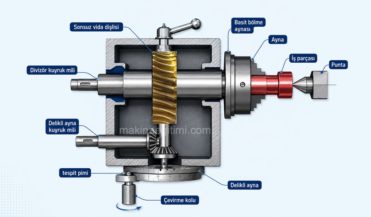
motion transmission in a dividing head

Indexing with a Dividing Head

You can find detailed explanations on this topic through the links below:

1- Circular (Radial) Indexing in Milling – Simple and Differential Indexing

2- Performing Linear Indexing in Milling – Ruler Graduation and Rack Gear Manufacturing

Rules to Follow When Performing Indexing Operations on a Milling Machine

  1. An indexing device suitable for the type of indexing operation must be selected.
  2. A cutter suitable for the indexing operation must be selected.
  3. A clamping method suitable for the job must be selected.
  4. The turning ratio (N) for the indexing device must be calculated according to the type of division, and the perforated chuck or notch must be selected according to the number of holes to be skipped.
  5. The turning lever’s position and sector arm settings must be made, and the clamping screws must be tightened.
  6. The accuracy of the turning amount and the sector arm opening must be checked.
  7. Before starting the cutting operation, the machine should be set up by calculating the spindle speed according to the feed rate, depth of cut, cutter diameter, and cutting speed.
  8. During hole-skipping, the current hole should be counted carefully before skipping.
  9. The turning lever should always be turned in the same direction, and backlash should always be taken up in the same direction. 10. If differential (compound) indexing is to be performed, the chuck locking screw’s locking pin should be open.
  10. After the turning operation, the turning lever’s pin should be inserted firmly into the hole

Related Posts
How to Read a Micrometer How to Read a Micrometer What Is Riveting. How Is It Done? What Is Riveting. How Is It Done? Work Instructions for a Cylindrical Grinding Machine Work Instructions for a Cylindrical Grinding Machine Tornada Kare vida açma Cutting a Square Thread on a Lathe Workplace Safety with Hand Tools Workplace Safety and Misuse of Hand Tools Lathe Tool Angles and Their Effect on Surface Quality Lathe Tool Angles and Their Effect on Surface Quality Information about end mill cutters Information About End Mill Cutters Types, Parts, and Maintenance of Dial Indicators Micrometers. Parts, Types, and Maintenance of a Micrometer

Milling
Share. Facebook Twitter WhatsApp Tumblr Email Telegram Copy Link

Leave A Reply Cancel Reply


Why Does the Battery Warning Light Come On? Signs of a Battery Fault
What Is Engine Braking? Does It Damage the Vehicle?
  • Contact
  • Terms of Service
  • Privacy & Cookie Policy

Type above and press Enter to search. Press Esc to cancel.