
Drilling on a Lathe
On a lathe, holes are drilled into the face of workpieces for various operations. These operations are center holes to support long parts, holes for tapping and reaming, or holes drilled to allow boring and internal facing.
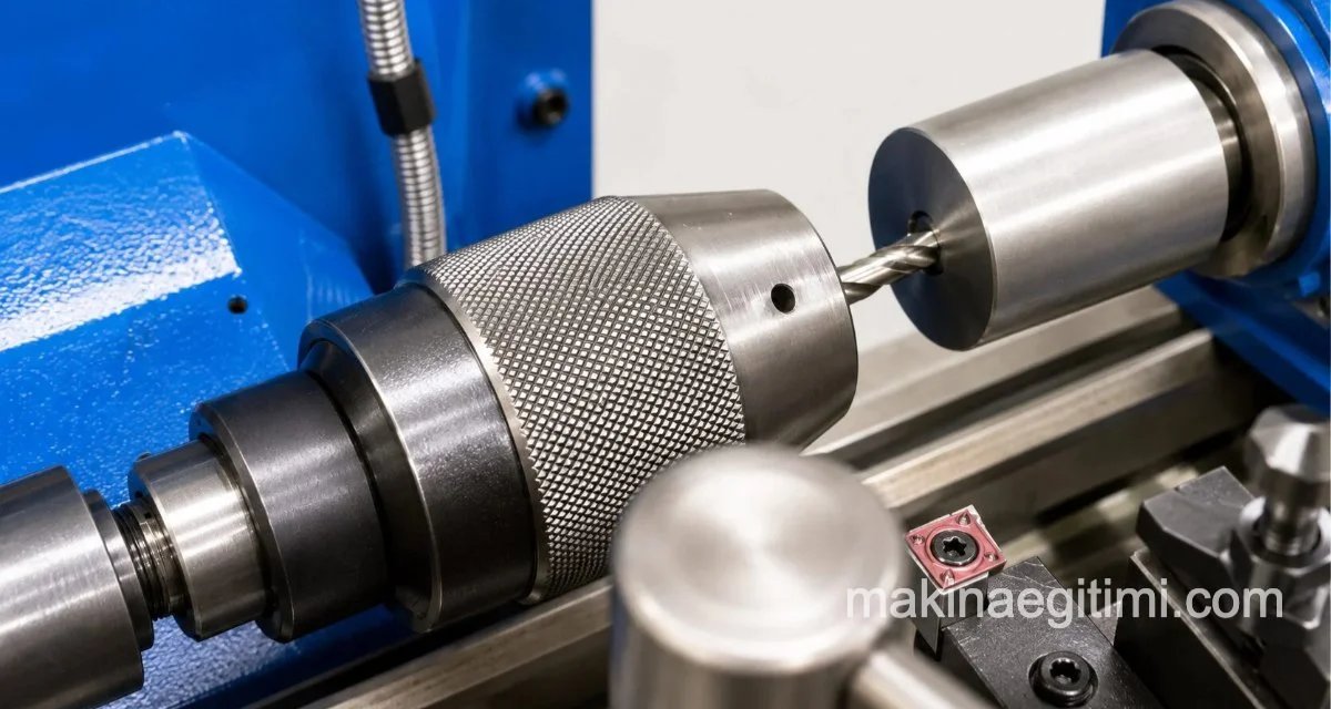
Drilling on a lathe is similar to drilling on a drill press, except that on a lathe the workpiece rotates instead of the drill. Drills are generally mounted to a lathe in two ways.
1- With a chuck 2- Directly into the tailstock
Mounting with a Chuck
A drill chuck is a tool used for mounting small- and medium-diameter drills (Ø1-16mm). The smallest and largest diameters that can be held in the chuck are printed on the chuck itself. The chuck has a shank that fits into the tapered hole (Morse taper) in the tailstock sleeve. When the chuck is pushed into the tailstock’s tapered hole, this tapered shank seats into the hole and the chuck is mounted. However, if the chuck’s tapered shank is smaller than the tailstock’s tapered hole, suitable Morse taper sleeves are used for mounting in such cases.
Mounting Directly into the Tailstock with a Morse Sleeve
Above Ø16, if drills have a tapered shank they’re mounted directly, and if they have a straight shank they’re mounted into the tailstock with the help of a Morse sleeve. Before drilling on a lathe, a center hole is drilled into the face of the workpiece to guide the drill, or a small countersink is made in the face of the work with a lathe tool.
On this topic, see: Making a Center Hole (Center Drill Seat) on a Lathe
Order of Operations for Drilling on a Lathe
The workpiece is mounted in the chuck appropriately for the job.
The drill chuck is fitted into the tailstock, and the center drill is mounted into the drill chuck.
The machine’s spindle speed is set appropriately for the center drill’s diameter.
The machine is started. The center drill is brought close by turning the tailstock handwheel by hand.

The center drill is fed in slowly to open a starting hole for the drill.
The drill of the desired size is mounted using the chuck, or directly into the tailstock sleeve.
The spindle speed appropriate for the drill diameter is selected.
The drill is fed into the work by turning the tailstock feed handwheel.
Note: Cutting fluid is used while drilling. When drilling deep holes, the drill is withdrawn frequently to clear chips.
Calculating Spindle Speed for Drilling on a Lathe
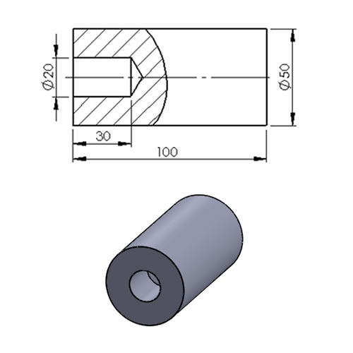
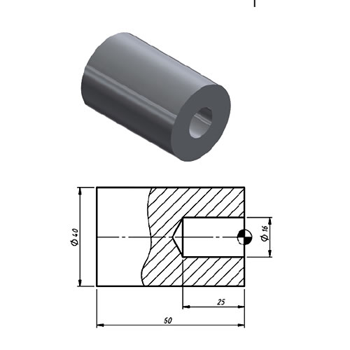
Example: A Ø20x30mm blind hole is to be drilled into a Ø50×100 mm workpiece. Given a cutting speed of V=20 m/min, calculate the spindle speed. (The drill diameters to be used are Ø5-11-20)
V= π . d . n / 1000
n= (V.1000) / 3.14 . d
n= (20.1000) / 3.14 . d
n1= 20000 / 3.14 . 5 = 1280 rpm
n2= 20000 / 3.14 . 11 = 580 rpm
n3= 20000 / 3.14 . 20 = 320 rpm
Boring Bar
Boring bars are made with specially angled tips to enlarge an existing hole to the desired diameter.
Vibration Risk
Thin and long boring bars can chatter on deep holes, degrading the surface finish.
Coolant Access
Getting coolant to reach the cutting zone during internal boring matters both for tool life and surface quality.
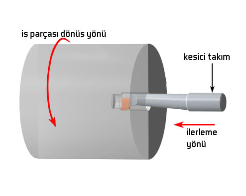
Boring – Enlarging a Hole
This is the process of enlarging a hole with a boring bar. To bore a hole, the hole in the part must already be large enough for the bar to enter, and there must be enough material allowance left to machine down to the final hole size.
To prevent the boring bar from chattering while boring, the largest boring bar that can freely enter the hole should be used. It’s possible to leave the desired amount of stock for finish machining and reaming the holes.
Order of Operations for Boring
1. The workpiece is mounted in the chuck running true.
2. The face of the work is faced off.
3. A hole is drilled to about 1mm smaller diameter and length than the desired final hole.
4. A boring bar of a suitable size for the hole is selected.
5. The boring bar is set at the height of the center axis.
6. The bar is fed along the length of the blind hole to bore it. When the bar reaches the bottom of the hole, it’s fed toward the center by turning the cross-slide screw.
7. Before each pass, the hole’s diameter and length are checked before machining.
Related Questions
On a drill press, the workpiece stays stationary and the rotating drill feeds toward it. On a lathe it’s the opposite: the workpiece rotates while the drill is held stationary and fed toward the part.
A drill chuck can only securely grip drills within a certain diameter range (generally up to Ø16). Larger drills are manufactured with a tapered shank and seated directly into the tailstock’s tapered hole, providing a sturdier connection.
Related Posts
 Micrometers. Parts, Types, and Maintenance of a Micrometer
  Drill Diameter Table for Taps
  Milling and Cutting with a Slitting Saw
  Johnson Gauge Blocks (Johansson Gauge Blocks) and Their Use What Is a Dial Indicator? How to Use It
  Hand Tools – Types of Wrenches
  Work Instructions for a Cylindrical Grinding Machine
  Universal Milling Machine Accessories