Close Menu
  • MAKİNELER ve İMALAT
    • Tools & Equipment
    • Computer-Aided Drawing
    • CAD/CAM Education
    • CNC Machine Programming
    • Casting Technologies
    • Electrical & Electronics Technologies
    • Hydraulics & Pneumatics
    • Manufacturing Processes
    • Manufacturing Technologies
    • Occupational Safety
    • Mold & Die Design
    • Solid Modeling
    • Welding Technology
    • Machine Elements
    • Mechanical Trade Drawing
    • Materials Science
    • Automotive & Vehicle Technologies
    • Robotics Technologies
    • Health Technologies
    • Defense & Aerospace Technologies
    • Descriptive Geometry
    • Technical Drawing
    • Software & Hardware Technologies
    • Innovative Manufacturing Methods
  • TEKNOLOJİ ve YAŞAM
    • OTOMOBİLLER ve TAŞIT
      • Vehicle & Engine Knowledge
      • Safe Driving
      • Sürüş Destek Sistemleri
    • Genel Kültür
      • Movies & TV Shows
      • Görsel ve Grafik Sanat
      • Books & Literature
      • Music
      • Sports
      • History
      • History of Technology
    • GÜNDELİK YAŞAM TEKNOLOJİLERİ
    • Hobbies & Entertainment
    • Internet Technologies
    • Health
    • Mobile Technologies
Makine Eğitimi
  • Machines & Manufacturing
    Machine Elements
    Hydraulics & Pneumatics
    Technical Drawing
    Computer-Aided Design & Manufacturing
    Basic Manufacturing Processes
    Manufacturing Processes
    Industry Technologies
    Other Technical Courses
    Motion & Power Transmission
    Simple Machines
    Chains & Sprockets
    Shafts & Journals
    Gears
    Cams
    Couplings
    Belts & Pulleys
    Springs
    Bearings
    Keys
    Fastening Joining
    Retaining Rings
    Screws, Bolts & Nuts
    Cotter Pins
    Flanges
    Welding
    Rivets
    Pins & Bolts
    Washers
    Calculators
    Gear Ratio Calculator
    Spring Constant Calculator
    Belt Pulley Ratio Calculator
    Other Machine Elements
    Slides & Linear Guides
    Brakes
    Flywheels
    Clamps
    Shock Absorbers
    Gaskets & O-Rings
    Seals & Sealing Elements
    Hydraulics
    Introduction to Hydraulics & Principles
    Hydraulic Systems & Applications
    Accumulators
    Filters
    Motors
    Pumps
    Valves
    Pneumatics
    Introduction to Pneumatics & Principles
    Pneumatic Systems & Applications
    Pneumatic Circuit Components
    Valves
    Cylinders
    Silencers
    Motors
    Compressors
    Dryers
    Conditioning Units
    Common Topics & Maintenance
    Hydraulic & Pneumatic Maintenance
    Study Notes, Exams & Tests
    Technical Drawing
    Introduction to Technical Drawing
    Geometric Drawings
    Perspective & Projection
    Orthographic Views
    Dimensioning
    Sectioning
    Assembly & Detail Drawings
    Tolerances
    Surface Finish Symbols
    Mechanical Engineering Drawing
    Screws, Bolts & Nuts
    Pulley Drawings
    Gear Drawings
    Shafts & Journals
    Bearing Drawings
    Pins & Bolts
    Spring Drawings
    Welds in Technical Drawing
    Washers
    Cotter Pins
    Technical Drawing Exercises
    Mechanical Drawing Exercises
    Gear Exercises
    View Extraction Exercises
    Pulley Exercises
    Pin & Bolt Exercises
    Threaded Fastening Exercises
    Descriptive Geometry
    Computer-Aided Drawing
    AutoCAD Drawing Lessons
    Computer-Aided Drawing Exams
    Solid Modeling & Animation
    Solid Model Drawing Files
    Solid Model Assembly Examples
    Solid Model Drawing Lessons
    3D CAD Software Reviews
    Solid Modeling Exercises
    CNC Programming
    CAM
    Measurement & Inspection
    Dial Indicators
    Calipers
    Gauges
    Micrometers
    Materials Science
    Steels
    Cast Iron
    Aluminum
    Plastics
    Material Testing & Hardness Measurement
    Occupational Safety
    Workshop Safety
    Safety When Working With Electricity
    Machine Safety Rules
    Hand Operations
    Filing
    Marking
    Cutting Operations
    Reaming
    Tapping
    Threading With a Die
    Drill Bit Sharpening
    Working With Machines
    Basic Turning Operations
    Basic Milling Operations
    Shaper Machine
    Machining
    Turning
    Milling
    Grinding
    Innovative Manufacturing Methods
    EDM (Electrical Discharge Machining)
    Laser Machining
    Waterjet Machining
    3D Printing
    3D Scanners
    Welding
    Rolling
    Casting
    Mold & Die Design
    Mechanical & Hydraulic Presses
    Blanking & Piercing Dies
    Bending Dies
    Drawing Dies
    Plastic Injection Molds
    Extrusion Dies
    Compound Dies
    Progressive Dies
    Blow Molds
    Spinning Dies
    Spray Molds
    Manufacturing of Machine Parts
    Automotive & Vehicle Technologies
    Motor Vehicle Manufacturing
    Raw Material Production
    History of Technology
    Health & Medical Technologies
    Defense & Aerospace
    Robotics Technologies
    Software & Hardware Technologies
    Mechanics - Strength of Materials
    Physics Topics
  • Technology & Life
    Hobbies & Entertainment
    Sports
    Music
    Vehicle & Engine Knowledge
    Vehicle Maintenance & Repair
    Safe Driving
    Driver Assistance Systems
    History
    Movies & TV Shows
    Books & Literature
    Computers & Internet
    Computer Tips
    Software Reviews
    Hardware & Peripherals
    Practical & Safe Internet Use
    Visual & Graphic Art
    Mobile Technologies
    Travel
    Science
    Health
    First Aid Knowledge
    Everyday Technologies
Makine Eğitimi
Home»Mold & Die Design»Die Clamping on Eccentric Presses
29 August 2026Updated:3 September 2026

Die Clamping on Eccentric Presses

Die Clamping on Eccentric Presses

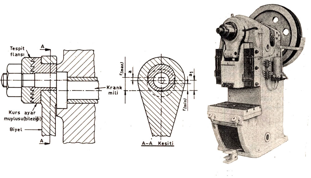
On today’s presses, the machine’s stroke capacity is set by the manufacturer using the graduations marked on the stroke adjustment collar that surrounds the crankshaft.

The safety bolt and key fitted to prevent the nut from loosening due to shock and vibration are removed, and the nut is loosened. It’s loosened by the distance the jaw clutch needs to rotate. Then, the stroke adjustment collar is turned via the shaft to achieve the desired stroke length.

Once the correct stroke setting has been made, the jaw clutch is clamped by tightening the nut, and the safety bolt is also tightened, completing the stroke adjustment.

The press ram is lowered to bottom dead center by hand using the flywheel. The die-clamping shoe on the ram is removed, and the die, with its die shank already attached, is placed into the ram’s socket. The shoe is fitted back in place, and its nuts are left without being fully tightened. 

Loosening the lock nut, the press ram is lowered to bottom dead center using the ball-head adjustment screw. The die is clamped tight. The die-shank clamping shoe screws on the ram are then fully tightened. 

The die is attached either with die-clamping shoes squeezed between the press ram and the press’s lower table, or with fasteners through slots machined into the die’s lower plate to match the press’s T-slots. When clamping, connections should be made at the points on the T-slots closest to the die, at a minimum of 2 points, without putting undue strain on the part being pressed.


The simple, basic principle for clamping to the press’s lower table using T-slots: the stud you’re attaching should always be as close as possible to the DIE.
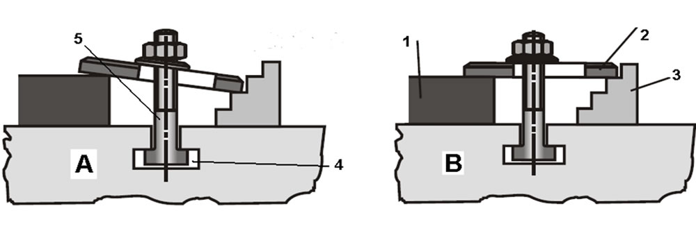
Clamping components. Clamping shoe, nut, washer, stud, and T-bolt (above)

The working gap of the die attached to the press is set below. It’s raised via the ram’s screw and adjusted to the correct position. After checking the connections, a trial run is done by turning the flywheel by hand. Then a no-load press cycle is run, and if that goes well, work on the press begins.

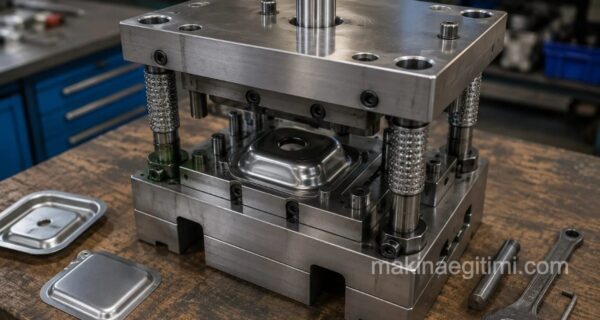
Attaching the lower die assembly to the press table (above)

To view and download this article as a PDF document, CLICK HERE

Die Zeroing Precision


The zeroing precision during die clamping on an eccentric press directly affects the dimensional accuracy of the part produced.

Clamping Components


Dies are fixed to the press table using T-nuts and clamping shoes.

Parallelism Check


Checking the parallelism between the upper and lower die is a critical clamping step that extends the die’s service life.

Related Questions

This bolt prevents the stroke adjustment collar from turning unintentionally during operation. It needs to be loosened before making the adjustment, otherwise the collar can’t be moved to the desired setting.

The gap between the die’s upper and lower halves can only be set correctly while the press is at its lowest position. Clamping in this position guarantees the die closes correctly during operation.

Related Posts

Stops and Side Gauges in Blanking Dies Stops and Side Gauges in Blanking Dies Birleşik Kalıplar Compound Dies drawing die carbide punch Carbide Dies and Punches in Drawing Dies Çekme Kalıbında Çekme Hızı ve Çekme Kuvveti Drawing Speed and Drawing Force in Drawing Dies cooling system in plastic injection molds Cooling System in Plastic Injection Molds A-form standard die shank Standard Die Shanks and Their Dimensions Kesme Kalıplarında Hareketli Baskı Plakası Blank Holder Plates and Ejector Plates in Blanking Dies How Is Aluminum Extrusion Done? What Is Aluminum Extrusion, How Is It Done?
Mechanical & Hydraulic Presses
Share. Facebook Twitter WhatsApp Tumblr Email Telegram Copy Link

Leave A Reply Cancel Reply


Fuel Pump Failure Symptoms
The October Revolution: How a Tsardom Fell Overnight
  • Contact
  • Terms of Service
  • Privacy & Cookie Policy

Type above and press Enter to search. Press Esc to cancel.