
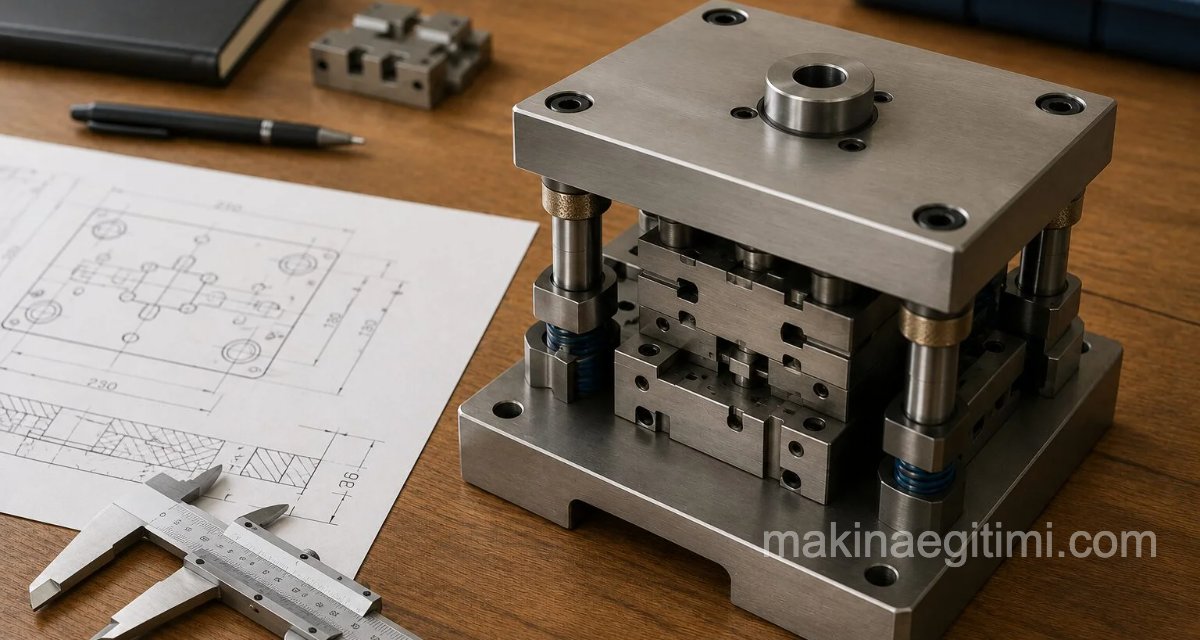
It’s possible to divide the mounting of punches onto the punch plate into 4 main groups.
- Punches with a Cylindrical Body and Tip Profile.
- Punches with a Cylindrical Body Profile and a Different Tip Profile.
- Closely Spaced Punches.
- Punches with Different Profiles.
Mounting Punches with a Cylindrical Body and Tip Profile

The mounting of punches with a cylindrical body and tip profile onto the punch plate is shown in the figure above.
Mounting Punches with a Cylindrical Body Profile and a Different Tip Profile
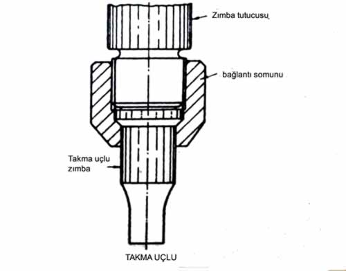
Punches with a cylindrical body profile and a different tip profile are mounted onto the punch plate in a way that prevents them from rotating around their own axis, so they can operate in the same position relative to the die.

The figure above shows the mounting of punches with a different tip profile onto the punch plate.
Mounting Closely Spaced Punches
When punches with very closely spaced axes are mounted onto the punch plate, a certain amount is removed from the punch shoulder heads. In dies with multiple punches, separate punch plates can be used for each punch group.
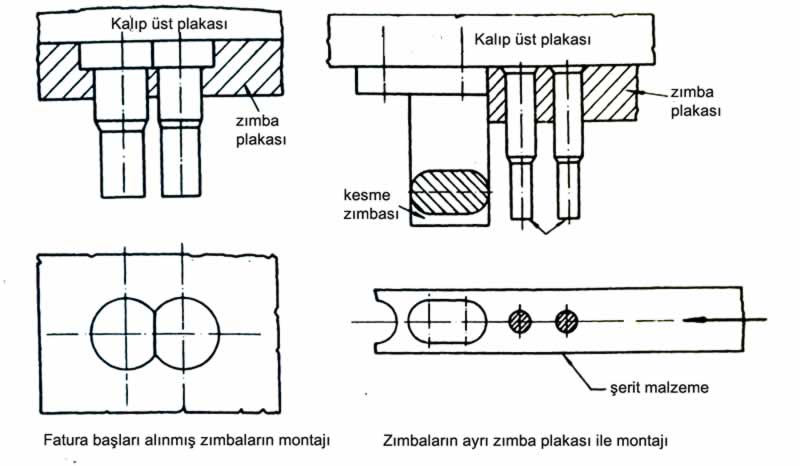
As seen in the example above, when building dies that use multiple punches, a separate punch plate can be used for each punch group.
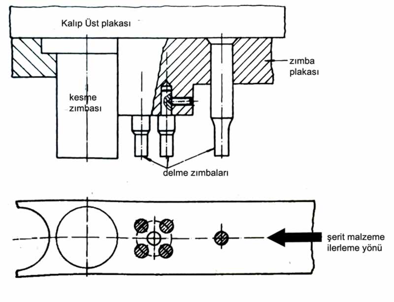
Mounting multiple punches onto the punch plate in cases with closely spaced axes (image above)
Mounting Punches with Different Profiles onto the Punch Plate
Punches with different profiles are mounted onto the punch plate in a way appropriate to the processing steps of the part being molded. Taking into account the three positions we discussed earlier, punches with different profiles are mounted onto the punch plates as shown in the figures below.
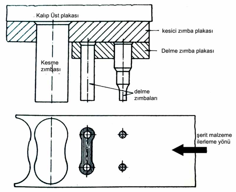
Mounting punches with different profiles onto the punch plate (below and above)

Related Posts
 Stripping Force and Punch Buckling Length Calculation
  Calculating the Cutting Force in Dies
  Blank Holder Plates and Ejector Plates in Blanking Dies
  Die Clamping on Eccentric Presses
  Cooling System in Plastic Injection Molds
  Washer Die Assembly and Detail Drawings – Dwg pdf
  Blank Diameter Calculation in Drawing Dies
  Bending Force Calculation for Bending Dies