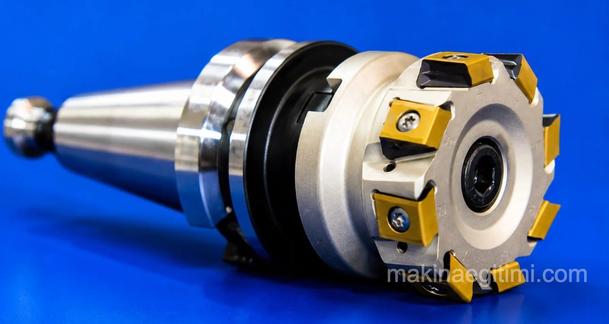
Cutting tools used on a milling machine — article contents:
The cutting tools used on milling machines are called milling cutters. Milling cutters are brought into contact with the workpiece to remove a certain amount of material from the part. For this operation, the cutter is rotated about its own axis. In other words, the workpiece and the cutter must be in motion relative to each other. Therefore, the relationship between the workpiece and the milling cutter must be well understood.
Properties of the Cutting Tools Used on a Milling Machine
In industry, milling operations most commonly use high-speed and carbide-tipped cutters, denoted by the abbreviation HSS. When we compare the tool bits used on lathes with milling cutters, each cutting edge of the milling cutter can be thought of as having the properties of a single lathe tool bit, which makes its economic value easier to understand.

Work carried out with incomplete or incorrect information can damage all the teeth around the cutter at once, considerably shortening the cutter’s service life.
Variety of End Mills
End mills are used in versatile milling operations, both for surfacing and for slotting.
Face Mill Efficiency
Face milling cutters are designed for fast, efficient machining of large flat surfaces.
Carbide-Tipped Tools
Milling cutters with replaceable carbide inserts offer the advantage of being able to run at high speeds and provide a long tool life.
Classification of the Cutting Tools Used on a Milling Machine
Sharp-tooth (pointed-tooth) milling cutters
These cutters are given rake and clearance angles on their cutting edges according to the type of material being cut. Because of these angles, which make the cutting conditions easier, milling cutters are generally made with sharp (pointed) teeth. They are used for slotting and cutting-off operations.
Form-relieved (constant-section) cutters
These cutters are used for milling various curves and profiles (gears, chains, sprockets, threads, etc.). To avoid distorting the profile, sharpening on these is done on the rake face.
Insert-type milling cutters
To reduce cost, in large-diameter cutters the body is made of tool steel or cast steel, with high-speed steel or carbide inserts mounted onto it. These can be used in any application.
Types of Cutting Tools Used on a Milling Machine
Plain (Straight-Tooth) Cylindrical Milling Cutters
These cutters, used for milling large flat surfaces, are made of high-speed steel. Since the cutting edges are parallel to the cutter axis, during cutting the teeth engage the material one after another along their full length at the same time, which places a heavy load on the cutter. This in turn causes impact and vibration. Since it becomes difficult to achieve a high-quality surface, these cutters are rarely made wider than 40 mm.
Cutters of this type with a small width/thickness can reasonably be called “slotting cutters.” Naturally, this is the cutter shape used for slot-milling work.
For milling large flat surfaces, thicker cutters of this kind can still be used despite the drawbacks noted above.
Cylindrical Helical (Slab) Milling Cutters
These milling cutters are also called “slab mills” or “roller mills” (because their teeth are helical), as well as “helical-tooth milling cutters.” They are cutters with numerous helical cutting teeth over a wide peripheral surface. Since they only have teeth on their periphery, they cut on one side only and are used for machining flat surfaces.
Because the teeth of the milling cutter engage the material being cut starting from a single point — that is, they enter gradually — they produce a quiet, vibration-free, and smooth cut. Compared to plain cylindrical milling cutters, a more efficient and higher-quality surface is obtained. They are well suited to heavy stock removal.

Face Milling Cutters
These are cutters with teeth on both their periphery and one face. Cutting is generally performed by the peripheral teeth. The teeth on the face act as support to the cutting periphery, producing a cleaner surface finish. During operation, the cutter’s face is parallel to the workpiece.
Feed is therefore achieved through cutting done by the peripheral teeth. Since the chip thickness does not change along the length of the cut, it’s possible to remove more material compared to cylindrical cutters. Since each tooth cuts its own chip thickness independently, the chip thickness does not change until the surface is fully milled. Since the cut is smooth, the cutter’s service life is also extended.

End Mills
These are shank-type milling cutters used for operations such as keyway cutting, milling helical grooves, cam making, forming curves, and countersinking/counterboring holes. End mills operate in a manner similar to face mills.
They are also called “shank-type cylindrical cutters” or “shaft-type cylindrical cutters.” Their shank shapes are made straight, tapered, or with a drawbar-thread hole. As for their tooth form, teeth are cut on both the periphery and the face as shown; for diameters above 6 mm, the peripheral teeth are cut as helical flutes. (They are like a small-diameter helical cylindrical mill.)
Those with two or three cutting edges/teeth around the periphery are used for cutting keyways and for drilling/hole-enlarging operations. Their cutting edges are ground so they can feed vertically, straight down into the material.
They are mounted to the milling machine using collet chucks and Morse taper sleeves. They are manufactured from high-speed steel according to the dimensions in TS 303.

End mills are among the most commonly used cutting tools on a milling machine.
Multi-purpose cutters of various types are used for milling keyways, deep vertical-walled slots, and for machining die/mold parts. Since heavy stock removal with the side faces of these cutters risks breaking the cutter, they should not be given too heavy a cut. Their cutting action can be thought of as similar to that of cylindrical helical mills, but they are weaker.
When dulled, larger-diameter ones are sharpened both on the periphery and on the face (until the full tooth depth is used up). Smaller-diameter ones cannot really be sharpened on the face. However, by hollowing the face slightly, they can still be used a bit longer for side-cutting operations.
For more detailed information about end mills, see: Information about end mills
Side and Slotting Milling Cutters
Since they have cutting teeth on three sides, they machine three surfaces at once.
There is quite a wide variety of side/slotting milling cutters, based on the shape of their cutting teeth. They are used, by means of the teeth on their periphery, for cutting and widening slots.

Plain-tooth slotting cutters are used for various slotting and cutting-off operations. Besides these operations, for many other jobs they are also used mounted on the same arbor with spacer collars between them, ganged as pairs, triples, or sets of four (as in the figure above). This allows facing opposite surfaces cleanly and in parallel.
The most commonly used type of side/slotting mill is the staggered-tooth slotting cutter, which is especially sought after for milling deep slots. During cutting, there is no heavy strain on the milling machine and efficiency is high. This is because they cut with the teeth on their periphery as well as on both side faces. Their teeth are staggered, alternating to the right and to the left.
They cut on alternating right and left sides. In staggered-tooth slotting cutters, the side teeth do not cut one right behind the other during operation. Since one side face of a tooth cuts and then the opposite side face of the next tooth cuts, there is no undue strain on the cutter. However, they dull quickly, because the chip load that would otherwise be removed by two teeth is loaded onto each tooth. There are also adjustable two-piece versions of this type of cutter, whose slot width can be adjusted.
Side/slotting cutters are generally sharpened “from the back,” and all their thickness dimensions change after sharpening.
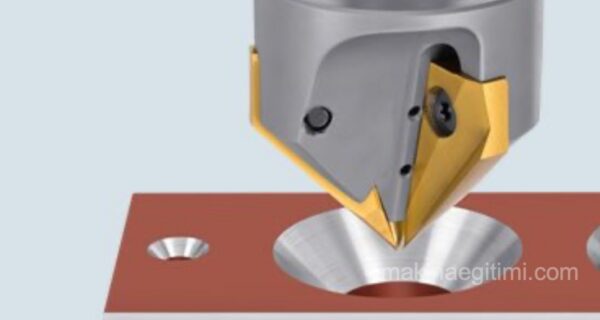
Angle Milling Cutters
Used for machining angled surfaces and grooves according to the value and type of the angle involved.

Cutting tools used on a milling machine – Angle milling cutters
T-Slot Milling Cutters:
These are used for machining the T-slots found in machine tables, the keyways along shafts, sliding fits, “Woodruff” key seats, and grooves of various shapes.
They are manufactured from high-speed steel according to the “T” slot dimensions used in machine construction. Because they are small in diameter, their shank is made as an integral part of the tool and mounted using collet chucks. During milling, since the cutter engages all three surfaces of the slot at once, heat builds up from the material being trapped inside. To prevent this, using coolant is essential. Clearing the chips out of the slot is also beneficial.
Considering these drawbacks when cutting “T” slots, the pocket is first roughed out within tolerance using a plain slotting cutter.

T-slot milling cutters and how a T-slot cutter is used in the milling process.
Form Milling Cutters
These are made in various shapes to give parts specific profiles. They are cutters used for machining various profile surfaces in order to obtain a particular profile. For cutting the profiles of reamer, drill, and tap flutes, these are milling cutters shaped, with a rounded tip on both sides (double-sided), to match the required clearance profile.

Form milling cutters and how a form cutter is used in the milling process. These tools, also called profile cutters or form cutters, can be said to be among the least commonly used cutting tools on a milling machine, since they’re used for special purposes.
Saw Milling Cutters (Slitting Saws)
These are slotting cutters with a thickness smaller than 5 mm, used for cutting-off operations. Cutting is done by the saw-shaped teeth around the periphery.

For a detailed article about milling and cutting with a slitting saw, see: milling and cutting with a slitting saw
Involute Gear (Module) Milling Cutters
Used for cutting standard gear profiles. Module cutters are standardized according to tooth size. Each set contains 8 or 16 milling cutters.

Module milling cutters are numbered from 1 to 8 or 16, and each number indicates which range of gear tooth counts it can cut

The meaning of the markings printed on module milling cutters (above)
For detailed information about module milling cutters, see: Information about module milling cutters
Gear Hobbing Cutters (Hobs)
Used for machining gear profiles completely and easily. Hobs are cutting tools used on special gear-hobbing machines. They belong to the milling-cutter class and are shaped like a screw thread, relieved on the back, in order to cut the profiles of spur and helical gears, worm gears, and similar parts.
Because they are difficult to manufacture, they are quite expensive. That’s because a single hob does the job that would otherwise require a set of 8 or 15 module cutters. It is therefore sufficient to have just one hob for each module.
On the face of a hob, the “module, pressure angle, and helix (lead) angle of the flute” are marked in degrees. (The helix flute is the tooth-relief channel cut around the periphery of this screw-like cutter, so that it can cut effectively.)

On this topic, see also: Gear Manufacturing by the Hobbing Method
Carbide-Tipped Milling Cutters
Used for machining harder materials. Manufactured as inserts, the tips are fixed to the body either by screwing them on or by hard-brazing. Because carbide-tipped milling cutters are suited to running at high cutting speeds, they are among the most commonly used cutting tools on a milling machine.

Related Questions
Each tooth around the cutter contacts the material in turn during rotation and performs its own small cut. Because of this, each tooth functions like an independently working cutting edge, and this perspective makes it easier to understand the cutter’s economic value.
An incorrect cutting speed or feed rate can cause all the teeth around the cutter to encounter an incorrect load at the same time as it rotates. This leads to wear or breakage spread across the whole cutter, rather than a single tooth, shortening the tool’s service life.
Related Posts