
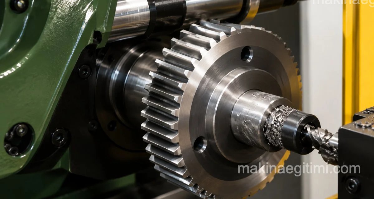
To make a worm wheel, we first need to determine the number of teeth for the worm wheel, and then calculate the worm wheel’s elements based on that tooth count.

To make the worm wheel on a universal milling machine, a module milling cutter and a dividing head are used. After the pre-milling operation is finished, a hob is used whose diameter, pitch, and helix angle equal the worm’s diameter, pitch, and helix angle. Hobbing is used to make sure the worm and the worm wheel mesh with each other perfectly.
Calculations for Making a Worm Wheel
When the worm wheel has 40 teeth, a single-start worm is used. For 40-50 teeth, a double-start worm is used, and for other tooth counts, a multi-start worm is used.
For good engagement, the worm wheel’s number of teeth must always be greater than 30.
To calculate a worm wheel, we’ll first use the table below. And with an example, we’ll calculate the elements of a worm wheel.
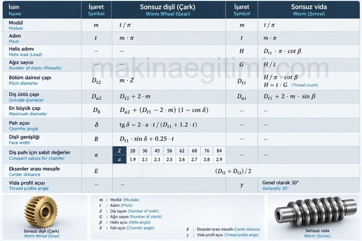
Example: A worm wheel with a module of 5 has 40 teeth, and the worm has 1 start. Find the worm wheel’s other elements. The worm’s pitch circle diameter is 42 mm.
Solution:
Pitch (t) = π . m = 3.14 . 5 = 15.7 mm.
Pitch circle diameter: (Dt2) = m.Z = 5.40 = 200mm.
Tip (outside) diameter (Da2) = Dt2 + 2m = 200 + 2 . 5 = 210mm
Root diameter (Df2) = Dt2 – 2.33 . m
= 200 – 2.33 . 5
= 188.35 mm

Tooth height (h) = 2.166 . m = 2.166 . 5
(h) = 10.83 mm.
Manufacturing Drawing of the Worm and Worm Wheel
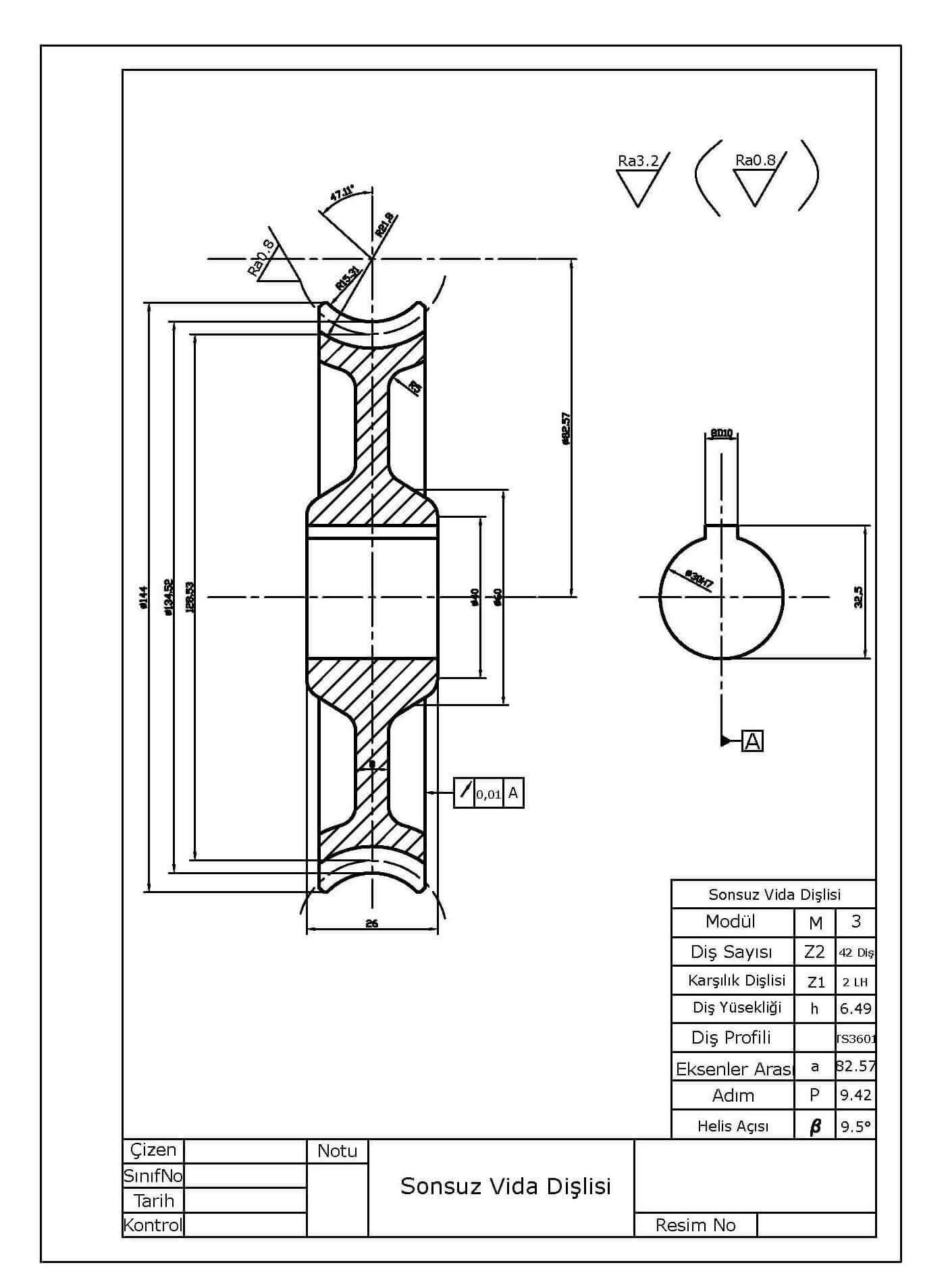
Download the worm wheel AutoCAD drawing
NOTE: Click the thumbnails to see the full-size manufacturing drawings with title blocks.


How Is a Worm Wheel Made?
— The worm wheel blank, turned to the required dimensions, is mounted appropriately between two centers using a mandrel, or between a chuck and a center.
— The module milling cutter, selected according to the worm wheel’s number of teeth, is mounted appropriately on the machine arbor or the head arbor. The machine table or the head is rotated in the correct direction by the helix setting angle and fixed in place. In this example the helix setting angle is large, so the head is used. The head is rotated 83°10′.
— The module milling cutter is set to the centerline. Cutting the worm wheel’s teeth is achieved mainly by moving the machine table up and down. For this reason, the module milling cutter must be set to the middle of the worm wheel’s width.

— The machine table is slowly raised to take a cut of the desired depth. This completes the pre-milling operation for one tooth. Don’t forget to zero the micrometer collar so that each cut is taken at the same depth. Fixed stops can also be used for this purpose.
— The machine table is lowered until the milling cutter clears the workpiece.
The index-plate crank handle;
(in the example, since Z = 40, T = K / Z = 40/40 = 1 turn)
is turned one full revolution to rotate the workpiece by one tooth. The machine table is slowly raised again to take a cut of the required depth.

All of the worm wheel’s teeth are machined the same way to finish the pre-milling operation. However, during pre-milling, some stock must be left for the finishing operation.
Finishing Operation for Making a Worm Wheel
— After the pre-milling operation is finished, a hob is used whose diameter, pitch, and helix angle equal the worm’s diameter, pitch, and helix angle.
A hob is a single-start worm. It has screw threads on it. The backs of its threads are relieved to form cutting edges. Hobbing is used to make sure the worm and the worm wheel mesh with each other perfectly. This is how the finishing operation is completed.
— The hob is mounted appropriately on the milling arbor. The worm wheel, mounted between the dividing head and the center, is fixed so it can rotate freely between the two centers.
— The milling machine is started, and the worm wheel is brought into mesh with the hob. As the hob operates, it both removes material from the wheel and rotates it.

— The machine table is slowly raised until the required tooth depth is reached, and the job is completed. Since raising the table gives a cut across all the teeth, the worm wheel must complete at least one full revolution for each cut to reach every tooth.
Related Posts
 Friction Materials Used in Clutches
  Pivot Pins – What Is a Pivot Pin, Where Is It Used
  Helical Gears
  What Is a Timing Belt? What Does It Do?
  What Is a Piston Ring, What Does It Do? Its Job and Installation.
  Metric-Whitworth Thread Tables
  Bearing Damage and Its Causes
  Bearing Selection. Which Bearing Is Used Where