
The workpiece clamping methods on a milling machine are as follows:
To mill industrial machine parts to consistent dimensions and shapes, various clamping arrangements, fixtures, and jigs are used. Workpieces being machined must not shift out of place and must be securely fixed. Otherwise, expensive cutters can break, and the tools they’re mounted in (arbors, collet chucks, etc.) can become damaged and lose their precision. Repairing or remaking these tools is also quite difficult.
How quickly a part can be clamped and unclamped on the machine matters, depending on its shape, surface geometry, precision requirements, and the number of pieces to be made. These are among the biggest factors affecting cost.
Taking these into account, workpieces are clamped to the machine using one of the following approaches.
Clamping With a Vise
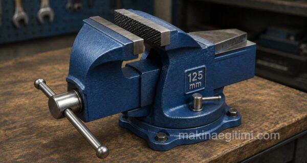
To clamp workpieces with a vise, the machine vise first needs to be mounted to the milling table. The keys under the machine vise are positioned so they sit in the table’s T-slots. Since both the table slots and the vise keys are ground, they fit together with a nice, snug slip fit. The vise is fixed to the table using T-nuts, studs, and hex nuts.
Related Post Mengene Çeşitleri Konu Anlatımı
Tesviyecilikte kullanılan mengene çeşitleri nelerdir.Üniversal mengene çeşitleri.Tezgah mengenesi çeşitleri.Özel amaçlı mengene çeşitleri.
Parallel bar heights are chosen so that about a third of the part to be clamped in the vise sits above the vise jaws. The part is lightly tightened with the vise screw. With this tightening, the part will be seen to rise up slightly. As shown in the figure, the parallels are held with our left hand. With the soft-faced hammer in our right hand, they are tapped lightly, without marring the part, so that the parallels don’t shift. Once it’s confirmed the parallels aren’t moving, the vise screw is tightened firmly, and after checking everything, milling can begin.
The jaws of the vises used should be checked from time to time with a dial indicator. A dial indicator is an inspection tool with a needle, accurate to 0.01 mm. Using its probe tip, which is linked to the needle inside its dial, the flatness and alignment of surfaces can be checked.
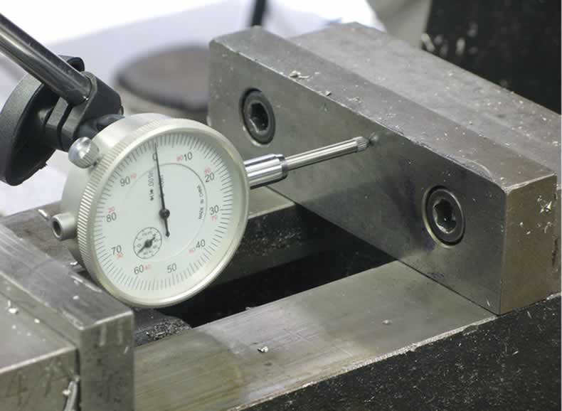
Checking, with a dial indicator, that the vise jaws are aligned with the machine’s axis (above)
In this procedure: after the vise is mounted to the table, before the probe tip touches the part, it should first be roughly aligned along the length by eye. Then the probe tip is brought into light contact with the part. (The needle inside the dial should be made to sweep at least five full turns.) At this position, the dial indicator is zeroed.
The table is moved lengthwise, right and left. The amount the needle deviates is read, based on the part’s alignment. The part, together with the vise, is rotated by half the deviation amount, the probe is swept again, and the process is repeated a few times.

Related Post Komparatör nedir nasıl kullanılır
Komparatör nasıl kullanılır, Komparatörler nasıl okunur. Komparatör okuma ve kullanımı. Komparatörün kısımları. Komparatörle salgı kontrolü.
Video: ensuring squareness of the parts to be clamped using a square (above)
Clamping With Bolts and Clamps
Parts whose shape makes them impossible to clamp in a machine vise are fixed directly to the machine table using auxiliary fixtures. This clamping is done with “Bolts and Clamps”, using the machine’s “T” slots
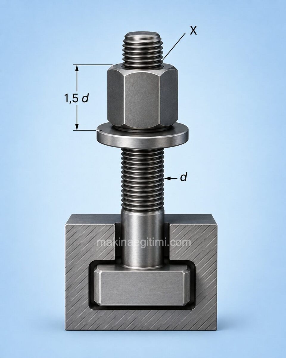
This consists of a “Bolt, Washer, and Nut” whose head is sized to fit the “T” slots on the milling table.

To allow the bolts to be used interchangeably in a set, they’re made as separate pieces, as shown in the figure. The bolt is made as a stud for economy. Because a frequently used bolt or nut would otherwise wear out at its threads. Another benefit of the parts being separate is that only the worn-out or damaged parts need to be replaced.
They’re manufactured in various sizes and lengths depending on the machine type. The bolt and head are sized based on the working conditions.
In the adjacent figure, showing a T-bolt seated in a ‘T’ slot, the bolt diameter is marked (d), and the nut’s height is specified as 1.5 d.
As for the dimensions of the bolt’s ‘T’ head, it should not be smaller than the machine’s slot. The ideal clearance is small enough that chips can’t get in between.
When tightening with the bolt, at least two threads must protrude above the nut after tightening. (Shown in the figure with an ‘X’ mark.)
Clamps and Parallels
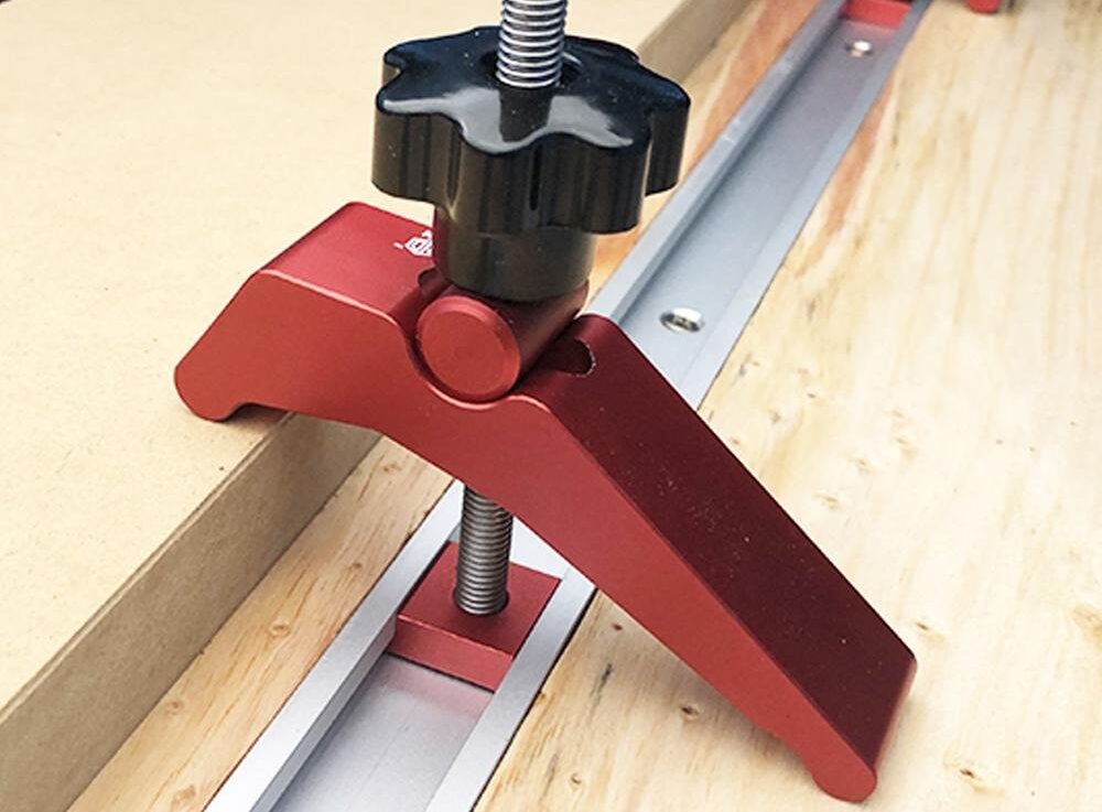
Clamps are the parts used, together with bolts, to hold down geometric or non-geometric parts that are too large to fit in a vise.

In the image above, we see a clamping operation done using a hold-down clamp and a support block.
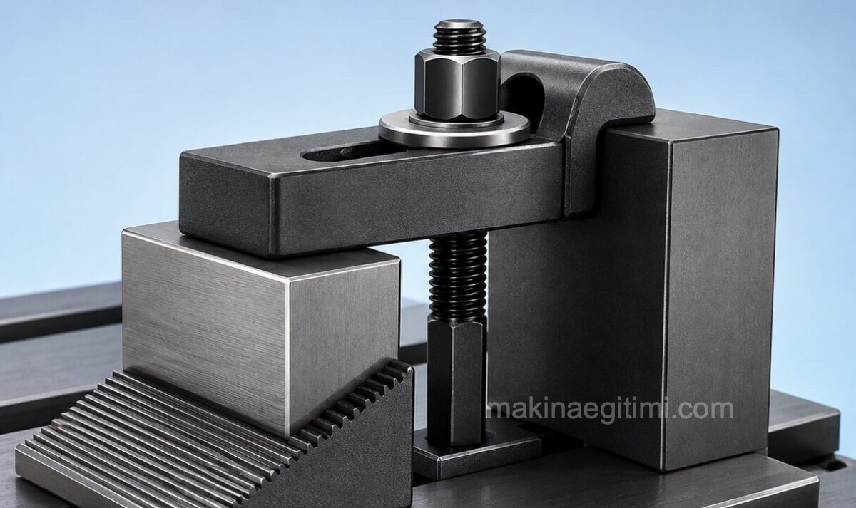
When clamping with hold-down clamps, holding the part firmly depends on the bolt’s center being close to the workpiece.

In the clamping arrangement with a bolt and clamp shown above, the distance (b) from the bolt to the workpiece should be smaller than the distance (a) to the support block.
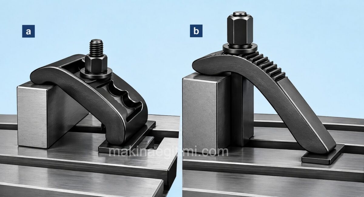
The figure above shows a workpiece to be milled, held down at an angle to the table using a different type of clamp. Here, the specially slotted washer under the nut prevents the bolt from sliding and the part from coming loose during clamping
Quick Clamping With a Vise
Vises allow standard-shaped parts to be clamped to the milling machine quickly and repeatably.
Flexibility of Bolts and Clamps
Clamping with bolts and clamps allows irregular or large parts to be fixed directly to the machine.
Rotary Table Precision
A rotary table allows the part to be rotated precisely during circular or angular milling operations.
Clamping With a Dividing Head and Tailstock
On milling machines, clamping regular cylindrical workpieces, or short and long shafts with center holes on their face surfaces, is done using a “Dividing Head and Tailstock.” The part is clamped along its axis using centers drilled into its two end faces.

Dividing head and tailstock
When milling with the dividing head in a horizontal position, if the part is long, clamping from one side alone isn’t enough. Therefore, a center hole should also be drilled into the other end of the part, and the work should be centered using the tailstock.
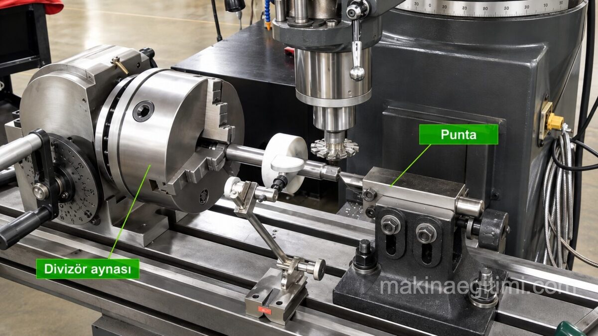
This kind of clamping is called “clamping between a chuck and tailstock.” If the part is shaft-shaped, a “steady rest” should also be placed at the middle of the shaft to prevent the part from deflecting during machining.
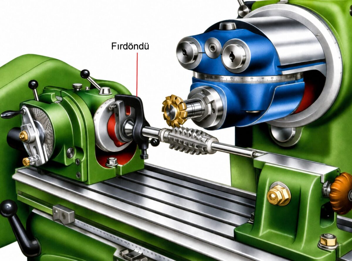
In some cases where clamping part of the workpiece in a chuck isn’t desired, the part is instead mounted between two centers using a driving plate and a driving dog. (Above)
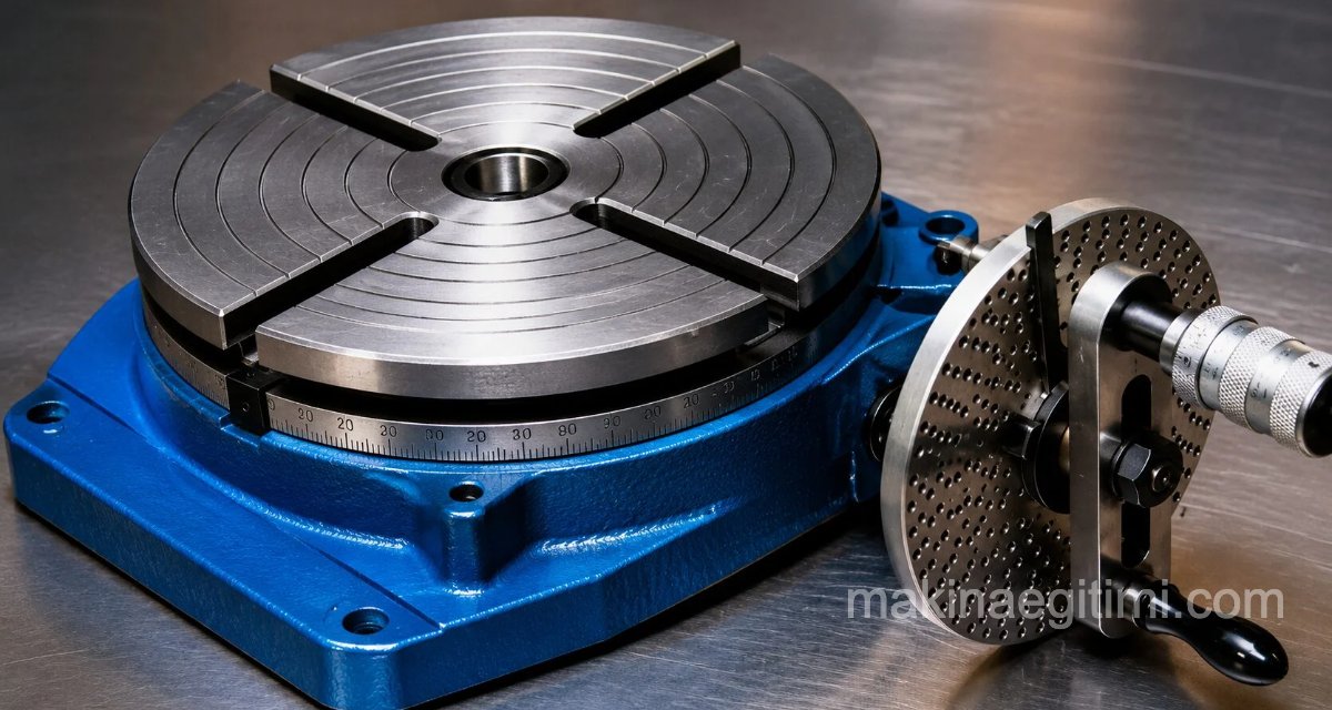
Clamping With a Rotary Table

Milling operations done on a rotary table are mostly used for: die/mold cavity work; circular milling of internal and external surfaces; marking out and machining cam profiles or surfaces; and cutting large-diameter internal and external spur gears.
If you look closely, you’ll notice the cylindrical part is clamped to the rotary table using hold-down clamps.
Having graduated divisions in degrees around the table also makes it easier to work at various angles.
Clamping With Special Jigs
When milling workpieces in a production run, having to clamp and unclamp each part individually, or having to fasten it with numerous bolts and clamps every single time, tires out the operator and makes the job tedious. This also slows down the workflow, which reduces production due to the time lost.
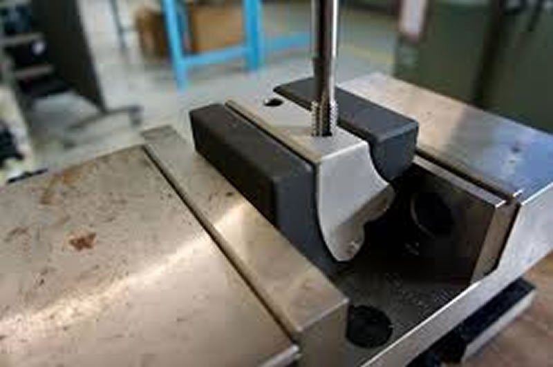
When machining large numbers of such parts, clamping methods and fixtures that require minimal effort are considered. Jigs that allow quick clamping and unclamping are the best solution. However, since building a jig for every job takes time, once the jig’s cost is factored into the price of the parts produced, the resulting per-unit manufacturing cost still needs to be low. Otherwise, it shouldn’t be done.
In jigs, clamping and unclamping should be very quick and practical. We can explain this practicality as follows. That is, clamping the workpiece on the machine table should happen with a single motion of a lever, wrench, or nut. Once the operation is finished, the part should again be removable from the table with a single motion.
Video: use of a fixture for clamping a cylindrical part on a milling machine (above)
Related Questions
If the part shifts during machining, it can strike the rotating cutter and break it. This can damage not just the cutter but also the precision components it’s mounted in, like the chuck or arbor, resulting in costly, hard-to-repair damage.
These keys ensure the vise sits fully and consistently aligned on the table. If the keys aren’t seated correctly, the vise can shift slightly, which can cause dimensional errors in the machined part.
Related Posts
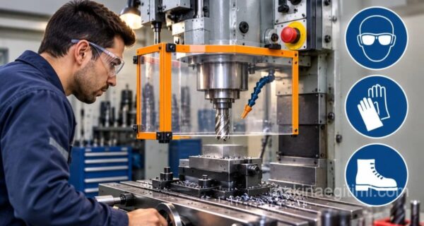 Safe Working Rules on a Milling Machine
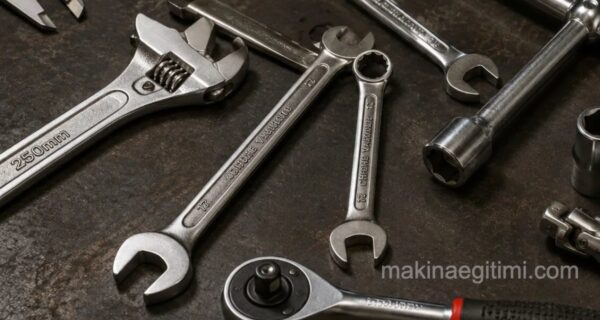 Hand Tools – Types of Wrenches
 Cutting Tools Used on a Milling Machine
 Mounting Grinding Wheels on the Machine
 Micrometer Simulator
 Changing the Jaws on a Universal Lathe Chuck
 Circular Indexing with a Dividing Head – Simple and Differential Indexing
 Work Instructions at a Drill Press