
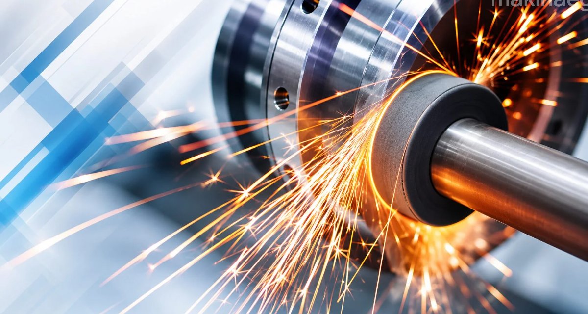
Mounting Grinding Wheels on the Machine
The components that mount a grinding wheel are described below. Spindle: the shaft that carries the grinding wheel, which spins at high RPM. Flange: located on both sides of the grinding wheel, contacts the wheel with its side surfaces and transmits the spindle’s rotational motion to the grinding wheel.
The center portion of the flange surfaces that touch the grinding wheel is relieved from the center outward. • The smooth, machined surfaces left outside the relieved area are what actually clamp the wheel.

Flange Diameter Dimensions
Flange diameters should be at least 2/3 of the wheel diameter. The diameters of the flanges clamping the wheel on either side must be equal to each other. If the wheel diameter is denoted (d), the flange diameter (S), and the flange’s clamping surface (b), the flange diameter calculation for straight and tapered wheels is as follows.
For a straight wheel: S = 2/3.d, b = 1/6.s
For a tapered wheel: S = 1/2.d, b = 1/6.s
Spindle Clamping Nut
Depending on the spindle’s direction of rotation, this ensures the flanges seat against the wheel’s surface and clamp it. Clamping nuts must be designed so they don’t loosen in the direction of rotation.
Wheel Bore Lead Bushing
For grinding wheels with lead in their bore, the bore diameter can be smaller or larger than the spindle diameter. If the bore diameter is smaller, it’s turned on a lathe so it can fit onto the spindle. To let the wheel fit onto the spindle with a light, snug fit, the bore diameter is made 0.15 to 0.20 mm larger than the spindle diameter.
If the bore diameter is larger than the spindle diameter, the lead bushing in the wheel’s bore is removed, lead is recast, and it’s turned on a lathe so it fits onto the spindle with a light, snug fit.
Gaskets
These are placed between the grinding wheel and the flange. They distribute the clamping pressure the flanges exert on the wheel’s surface evenly, ensuring the clamping is done properly. They’re cut from, or purchased in, materials such as felt, leather, rubber, or cardboard. The gaskets’ diameter is larger than the flange diameter; their thickness is between 0.5 and 0.75 mm.
Precautions to Take When Mounting Grinding Wheels on the Machine
- Grinding wheels should be inspected before being mounted in place; cracked or damaged ones must not be used.
- When mounting a grinding wheel on the machine, suitable gaskets made of a soft material such as paper, rubber, or leather — with a diameter no smaller than the flange diameter — should be placed between the flange and the wheel.
- The spindles the grinding wheel is mounted on must be properly constructed and supported to specification, must rotate without runout, and the clamping nuts must be threaded so they don’t loosen in the direction of rotation.
- Grinding wheels that don’t comply with the manufacturer’s specified standards must not be used on machines.

Grinding wheel labels contain data such as the wheel’s dimensions and maximum operating speed
- Grinding wheels must not be operated above the speed specified by the manufacturer.
- The label showing the wheel’s standard specifications, affixed to the wheel, must not be removed.
- The side faces of straight-face grinding wheels must not be used.
Ring Testing a Grinding Wheel With the Handle of a Screwdriver

Checking a grinding wheel for cracks
Before even considering mounting a new (or used) grinding wheel, do the following: hold it with a screwdriver and tap its side surface lightly with the handle of another one.
We need to touch the wheel with something solid but non-metallic. A screwdriver or similar tool’s hard plastic or hard wooden handle is ideal.
You should hear a nice, clear metallic ring. If not, the wheel may be cracked, and there’s a high chance it could shatter once it’s up to speed. You should consider getting rid of that wheel.
Related Posts
 Micrometers. Parts, Types, and Maintenance of a Micrometer
  Cutting a Square Thread on a Lathe
  What Is Marking? What Are the Marking Tools?
  Work Instructions at a Drill Press
  Work Instructions for a Cylindrical Grinding Machine
  Cutting Speed – RPM Calculator
  What Is an Automatic Lathe, How Does It Work?
  How to Read a Micrometer