We’ve dedicated this article to splined shafts. We’ll cover details such as what a splined shaft is, where a splined shaft is used, the standard designation of splined shafts, and splined shaft dimensions.
Splined Shaft
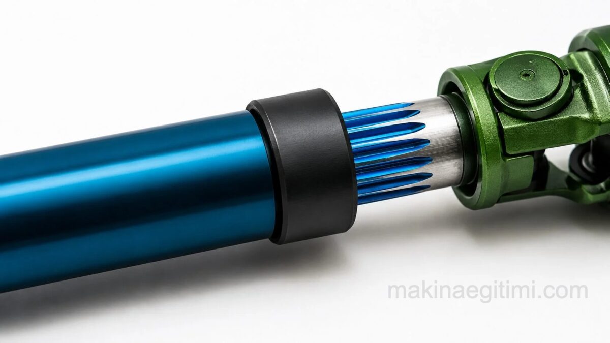
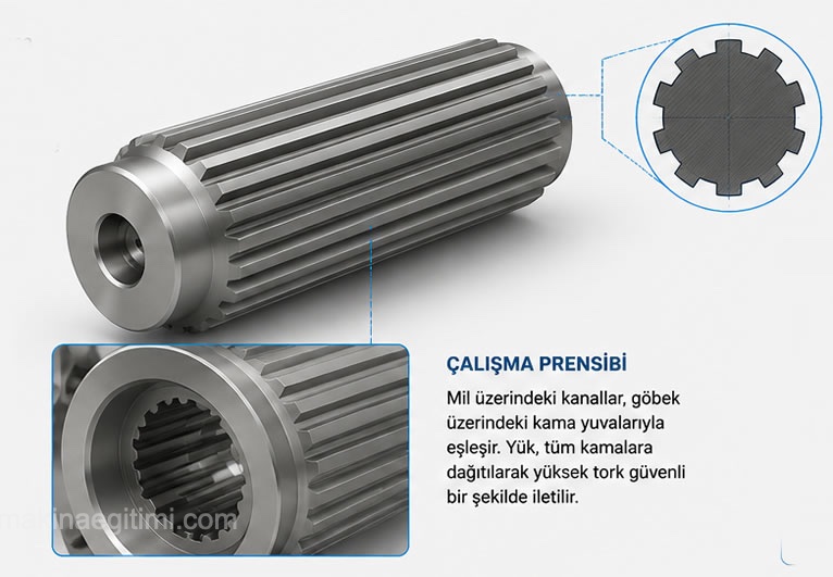
Unlike ordinary shafts, splined shafts have grooves cut at regular intervals along the shaft axis. The purpose of cutting these grooves is to fix machine elements such as gears, pulleys, and flanges onto the shaft so that torque and rotational motion from the shaft are transmitted to these machine elements.
Advantage of Splined Shafts
In shafts made with a single keyway, the load is concentrated on that single key. As a result, in some cases the key cannot bear the load placed on it and breaks.
In a splined shaft, however, the load is distributed across all the splines. It doesn’t slip or develop play. It’s safer.

Torque Transmission
Splined shafts safely transmit torque by preventing elements such as gears and pulleys from rotating independently of the shaft.
Standard Spline Groove
Spline groove dimensions are defined in tables set by standards such as DIN and ISO, based on shaft diameter.
Shear Stress Risk
In splined shaft connections, shear stress can build up on the splines under excessive load, leading to failure.
Where Is a Splined Shaft Used?
In heavily loaded motion-transmitting elements, a single key may not be able to bear the force. Splined shafts are used in such cases.
They’re used in motor vehicles, in heavily loaded transmission gearboxes and similar places.

Splined shafts are preferred wherever high torque transmission is involved. The load a shaft with many spline grooves cut into it can carry will be more than the load you can carry with a single keyway and key.
Universal joint couplings are used in vehicles for rotational motion and high torque transmission.
For detailed information about couplings, SEE: Couplings and Types of Couplings
Standard Designation of Splined Shafts
Splined shafts are standardized under Turkish Standards, grouped into four categories.
TS 147/15 gives the dimensions of the light type, TS 147/16 the medium type, TS 147/18 the 4-spline type used on machine tools, and TS 147/19 the 6-spline type used on machine tools.
The designation of a light-type splined shaft profile with 6 splines, an inner diameter of 28 mm, and an outer diameter of 32 mm is written as “splined shaft profile B6 x 28 x 32 x TS 147/15,” and the designation of the hub profile is written as “splined hub profile A6 x 28 x 32 x TS 147/15“

The representation of splines used on machine tools in drawings is shown above. As shown in the figure, a schematic drawing of the splined shaft is made, and its properties are specified with symbols.
The designation above ( A42 J6 X 48 X 10 TS 147/19) is for a 6-spline splined shaft used on machine tools, with an inner diameter of 42 mm, an inner diameter tolerance of J6, an outer diameter of 48 mm, and a spline width of 10 mm. In this type of splined shaft, the letter A is used if the splines are made with a hob cutter, and the letter B if they’re cut with a face milling cutter.

Example Splined Shaft Drawings


Example splined shaft drawings are given in the images.

Splined Shaft Dimensions

Standard splined shaft dimensions are given above. You can click the image to examine it more closely.
Related Questions
In a shaft with a single key, the entire load is concentrated on that one key, and this key can break under excessive load. In a splined shaft, however, the load is distributed evenly across multiple grooves around the shaft, reducing the risk of excessive stress at a single point.
The grooves on the shaft interlock with matching grooves on the inner surface of the part mounted onto it. This physical interlocking allows the two parts to rotate together without slipping relative to each other.
Related Posts