
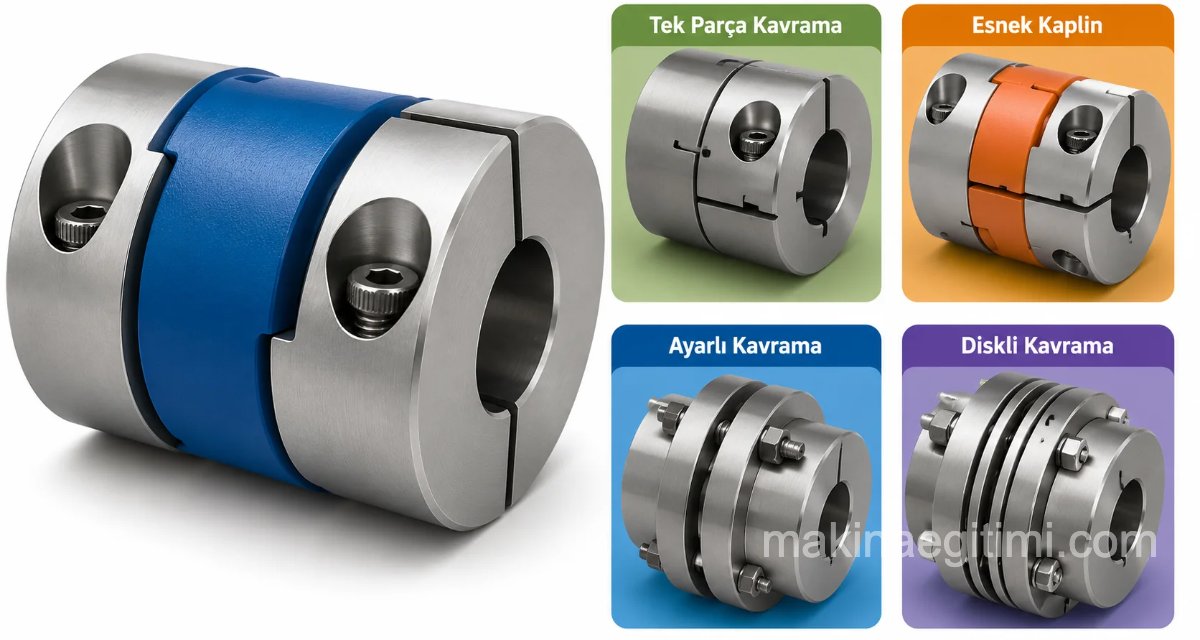
One of the parts that comes to mind when we talk about machine elements is couplings. We’ve dedicated this article to couplings, where they’re used, and the types of couplings.
Couplings are machine elements that join shafts on the same axis, transmitting force and motion between them either rigidly, with movement allowed, flexibly, or in a way that can be disengaged.
Where Couplings Are Used
1- Stopping or restarting one shaft at will, without stopping the engine shaft, is done through coupled connections. The area where couplings are most commonly used is in vehicles, where the clutch engages and disengages the rear wheel’s motion.

Pedal control of a clutch coupling used in motor vehicles. This coupling is normally engaged by spring force. The driver disengages it by pressing the pedal. Here, hydraulic cylinders are used to reduce the pedal force required.
2- Cutting off the flow of energy to the driven side, or reversing the direction of rotation, with a suitable combination, without stopping the driving side or reversing its direction. These types of systems are generally called reversing mechanisms.
3- Transmitting motion from a single driving element (for example, a single diesel engine) to different parts of the system, and disconnecting it when desired. (For example, mobile rotating tower cranes with a bucket)
It’s important for couplings to run in balance. If they run out of balance, they damage the shaft ends. They also run inefficiently.

RIGID COUPLINGS
These are couplings that don’t disengage while transmitting motion from one shaft to another.
Ring (Clamp) Coupling
Made of two half-sleeves with a tapered exterior, joined by bringing the shafts end to end. To hold these two half-sleeves together, rings are fitted over the outside from both sides, tightening the coupling. It’s widely used because it’s easy to install and remove. Preferred in damp locations.

Sleeve (Muff) Coupling:
Two shafts with keyways are brought end to end and a sleeve is fitted over them. Gib-head tapered keys are driven in to secure it. Protective sheet-metal covers are fitted on both sides.

Split Sleeve Coupling
In this type, called a split sleeve coupling, made from two cup-shaped halves, the shafts are brought end to end and the two halves are fitted on. They’re tightened with bolts and nuts. A round sheet-metal guard is placed around the outside to prevent accidents.

Flange Couplings
Plate-shaped flanges with bolt holes around their circumference are fitted onto the shaft ends, either shrink-fitted (heated) or by hydraulic fit. Two-piece centering rings are placed between the flanges for alignment, and they’re tightened together with bolts and nuts. Gaskets are inserted between them wherever sealing matters.

Sellers Coupling
In this type of coupling, two tapered sleeves are drawn together inside a cylinder using three long bolts, bringing the shafts end to end. Since the bolts pass through both the sleeves and the cylinder, the coupling parts are prevented from rotating relative to each other.

In the Sellers coupling, the taper is between 1:10 and 1:20.
Face (Butt) Coupling
Thread-like teeth are cut into the face of the coupling parts, and it’s used to join hollow shafts. The coupling parts are brought together and locked in place.

Hydraulic (Oil-Injection) Coupling
In this coupling, made using hydraulic clamping methods, a jacket (1) with a tapered outer surface is first fitted onto the outside of the shaft. Then sleeve (2) is fitted on and nut (3) is threaded on. Then, using pumps (4), oil with a viscosity of 3 Engler degrees is pumped at 50°C between the sleeve and the jacket. Once the oil comes out at the end of the coupling, oil is sent from pump (5) to chamber (6). The sleeve, pushed by the pressure of the oil being sent, is forced against the jacket’s tapered surface.

FLEXIBLE-MOTION COUPLINGS
Expansion Coupling

In some cases, shafts operate under the effect of heat. Since a heated shaft can elongate 1.1 mm per 1 m of length at 100°C along its axis, this type of expansion coupling accommodates this. Made with finger-shaped protrusions and recesses, this coupling leaves an allowance for elongation.
Oldham Coupling

Types of couplings – Oldham coupling
Used when there’s a parallel offset between shafts. This offset is accommodated by placing a slotted disc part between the two coupling halves, with the slots perpendicular to each other.
Cardan (Universal) Joint
Used in situations where shafts need to operate at an angle to each other (for example, at the ends of a vehicle’s driveshaft).

This angle is around 5°-7°. A Cardan joint is made up of two fork hubs and a cross-shaped spider. The fork hubs, mounted to the shaft ends, are connected to each other via the spider.
How a Cardan joint operates – animation
Constant Velocity (CV) Joint
Since Cardan joints only operate at limited angles like 5°-7°, constant velocity joints are used whenever motion is needed at larger, or unchanging, angles. Elements like rollers, gears, etc. can be used.


In constant velocity joints, when two shafts operate at angle (a), the constant velocity plane (the balls) can operate at up to a/2.
FLEXIBLE COUPLINGS
Designed to accommodate flexibility against various shocks and impacts machines experience while running, and misalignment errors in the system, flexible couplings, made from flexible materials (leather, springs, rubber, etc.), help transmit motion smoothly. These are:
Periflex Coupling
Widely used in industry, this coupling has a ring made from fabric-reinforced rubber, connected to the flanges with the help of retaining rings.


Types of couplings – Periflex coupling, section view. These couplings can safely accommodate about 8 mm of axial movement, 5 mm of radial movement, and 3-5° of angular movement.
Thanks to their elastic nature, they handle incoming moments exceptionally well. In places where centering is difficult, they give good results when used together with multi-disc or electromagnetic clutches.
Elastic Bushed-Pin Coupling
Elastic bushings are placed into holes in the flanges mounted to the shaft ends, and the two flanges are drawn together and connected using elements like bolts or pins. These are suitable for eliminating perpendicular and axial forces, shocks, and impacts coming onto the shafts.
Bibby Coupling
Grooves are cut around the circumference of flanges keyed onto the ends of the two shafts, and this coupling is formed by fitting coiled springs with a rectangular cross-section into these grooves. The springs are made from high-quality spring steel. They can be used safely under shock loads.

Voith-Mourer Coupling
Formed by arranging coiled springs, numbered (3), inside flanges numbered (1) and (2) shown in the figure. They can accommodate up to 2-3 mm of axial movement, and 1°-2° of angular movement.

Coupling with a Free Elastic Insert
In this coupling, parts made of rubber or a similar elastic material, numbered (3) in the figure, are placed between flanges numbered (1) and (2) to provide elasticity; the elastic parts are held in place by protrusions or pins.

DISENGAGEABLE COUPLINGS (CLUTCHES)
Multi-Disc Clutch

This is a type of clutch made by creating a large number of friction surfaces. The many friction surfaces (discs/plates) are there to increase the friction force. In places where centering is difficult, it gives good results when used together with electromagnetic clutches.
Hydraulic Multi-Disc Clutch
These clutches, operated with pressurized oil, have a wide range of uses. As shown in the figure, when pressurized oil is fed to pipe (a) through the four-way valve (4), oil in pipe (b) returns to the oil tank through pipe (d). This way, as pressurized oil fills chamber (a1) of the cylinder, the oil in chamber (b1) drains out. As a result, one clutch closes while the other opens. If pressurized oil is sent through pipe (b), the opposite of what was described above happens. Engagement occurs as a result of this opening and closing.
Friction Clutch
A friction clutch is a type of clutch that joins shafts by generating friction force through disc-shaped parts with friction surfaces mounted on the shaft ends, transmitting motion to the other shaft.
When the disc on the driving shaft is pressed against the disc on the other shaft, motion is transmitted through friction between their surfaces.

Rigid Couplings
Rigid couplings provide continuous power transmission by permanently joining two shafts on the same axis.
Flexible Couplings
Flexible couplings reduce vibration by tolerating small misalignments between shafts.
Clutch-Type Couplings
Clutch (disengageable) couplings let you engage or disengage power transmission whenever needed, giving you control.
Dog (Jaw) Clutch

Claw-shaped flanges are mounted onto the shaft ends, and motion is transmitted from one shaft to the other this way. When lever (1) is pressed in the direction of the arrow, the clutch engages. When pulled the opposite way, the clutch disengages.
Pneumatic Clutch
This is a type of clutch operated with air. Pressurized air coming from a hole in the middle of the shaft pushes part (a) toward the discs, engaging the clutch. When the air is released, spring-loaded bolts on part (a) disengage the clutch and return part (a) to its original position, stopping motion transmission.
Pneumatic Friction Clutch
In this air-operated clutch, pressurized air coming through a hole in the middle of the shaft enters through pipe number (5), inflating air bladder number (3) and pressing it against drum number (1). This transmits motion to the other shaft. Figure: 4.64
Hydrodynamic (Fluid) Coupling

Widely used in water turbines at dams, in ships, and in vehicle engine gearboxes, this type of coupling operates on hydraulic principles. In vehicle engines, they’re a great help in smoothly getting past the “dead point where turning torque can’t be transmitted,” which is the main drawback of this setup.
Also called turbine couplings, these couplings have some outstanding advantages.
1. They run smoothly and without shock.
2. They accelerate evenly.
3. They’re resistant to overloading.
4. They have a long service life.
5. Even if the driven shaft stops, the engine keeps running.

Automatic (Centrifugal) Clutch
This is a type of clutch that engages and disengages on its own without being controlled. As the shaft rotates, spring-loaded friction shoes on the driving shaft open outward due to centrifugal force as speed increases, rubbing against the inner walls of the opposing shaft and transmitting motion to it.
Also called automatic safety clutches, in this coupling system, braking a vehicle causes the spring-loaded shoes to open and rub against the wheels, applying the brake.
Electromagnetic Clutch
These are clutches that engage and disengage by creating a magnetic field with electric current between the two parts to be coupled. They can be controlled remotely. They’re often used in places that need to engage and disengage very quickly (rolling mills, sheet-metal shears, cranes, presses, shapers, elevators, automatically operated machine tools). Current consumption is low.
Related Questions
This design ensures that engine power is transmitted to the transmission uninterrupted as long as the driver isn’t doing anything. The driver only temporarily breaks this connection by pressing the pedal when they want to shift gears.
The hydraulic cylinder amplifies the small force applied to the pedal, letting it overcome the clutch’s strong spring resistance with less effort. This helps the driver spend less physical effort while pressing the pedal.
Related Posts
 Friction Materials Used in Clutches
 Plain (Sliding-Contact) Bearings
 Differences Between Leaf Spring and Coil Spring Suspension
 What Is a Splined Shaft. Where Is a Splined Shaft Used?
 Bearing Selection. Which Bearing Is Used Where
 Motion Transmission with Belt Pulleys
 Rack Gears and Their Applications
 Applications of Plain Bearings