This article will cover helical gears in detail. What is a helical gear. How is it made. How does it differ from a spur gear. Advantages of helical gears. Areas of use. We’ll touch on topics such as how a helical gear is manufactured. Here are the topics:
Helical Gears
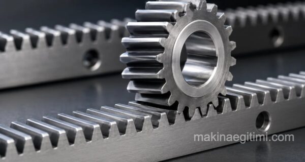
Differences Between Helical Gears and Spur Gears
Spur gears run noisily and with impact. To prevent this impact and noise, gears are made helical instead.

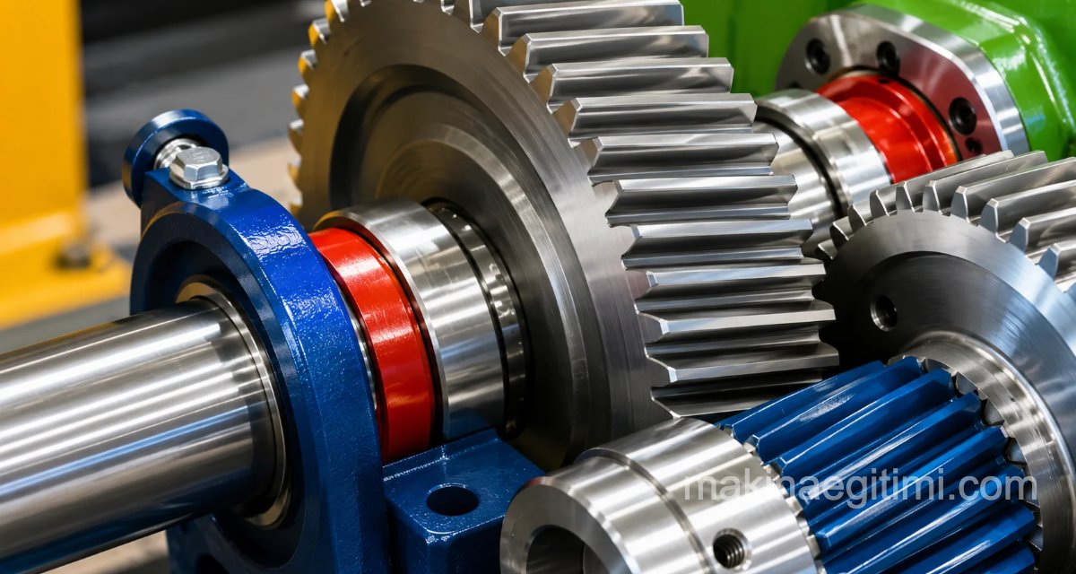
The visual difference between helical gears and spur gears. The teeth are angled instead of being parallel to the shaft axis
While spur gear shafts must always be parallel to each other, helical gears can operate both on parallel shafts and at various other angles.
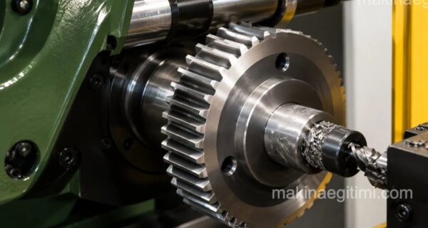
What is a helical gear? Helical gears are a type of gear and machine element used to transmit motion and force between shafts that are close to each other.
Helical gears outperform spur gears in terms of quiet operation and strength. Helical gears are named right-hand or left-hand helical, based on the direction their teeth are cut.
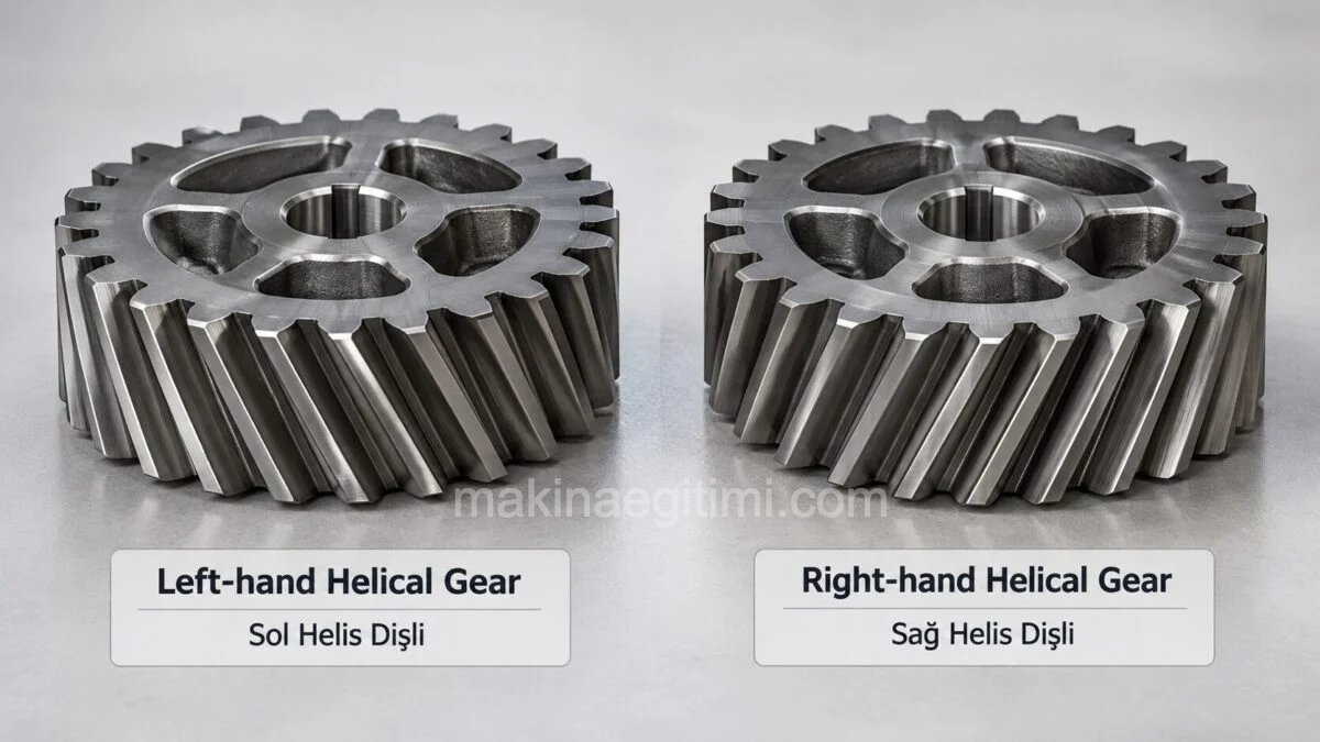
Helix direction on gears. When we lay the gear down, if the teeth rise toward the left, it’s called a left-hand helix. If the teeth rise toward the right, it’s called a right-hand helix.
Advantages of Helical Gears
- They run more quietly and with less impact than spur gears
- Helical gears are suited to angled motion transmission, which spur gears aren’t capable of.
- They mesh solidly and transmit motion with smooth engagement

Where Are Helical Gears Used

Helical gears are generally used in vehicle transmissions. In transmissions, we see that helical gears’ advantages of smooth engagement and lower noise are put to use.
For example, you’ll notice a different sound when you put a car in reverse. This is because the reverse gear in the transmission is a spur gear, not a helical one. (Below)

The reason a vehicle makes more noise in reverse is that the reverse gear in the transmission is a spur gear.
Areas of Use for Helical Gears

Example use of helical gears: differential (spiral bevel gears used here)


Although helical gears are generally used in the gearboxes/transmissions of vehicles or machine tools, the areas where helical gears are used can vary widely depending on the application


A view of the transmission (gearbox) system used in motor vehicles. Here too we see that helical gears are used.
As an example of helical gear applications, you can see how a manual transmission works and its helical gears in the video above.
Helical Gear Manufacturing Methods
The curves of helical gears are formed from cycloidal, involute, hypocycloidal, and epicycloidal curves.

Cutting Helical Gear Teeth
- By casting
- By machining with module cutters on copy-milling machines
- By rolling (form rolling)
- By press forming
- They are cut by hobbing methods on machines that work by the generating (rolling) method (Maag – Fellows).


Helical Gear Formulas
Below is a formula table for helical gears. At the top of the formula table, you can see how the terms in the formulas are represented on a gear drawing (which formula refers to which feature).
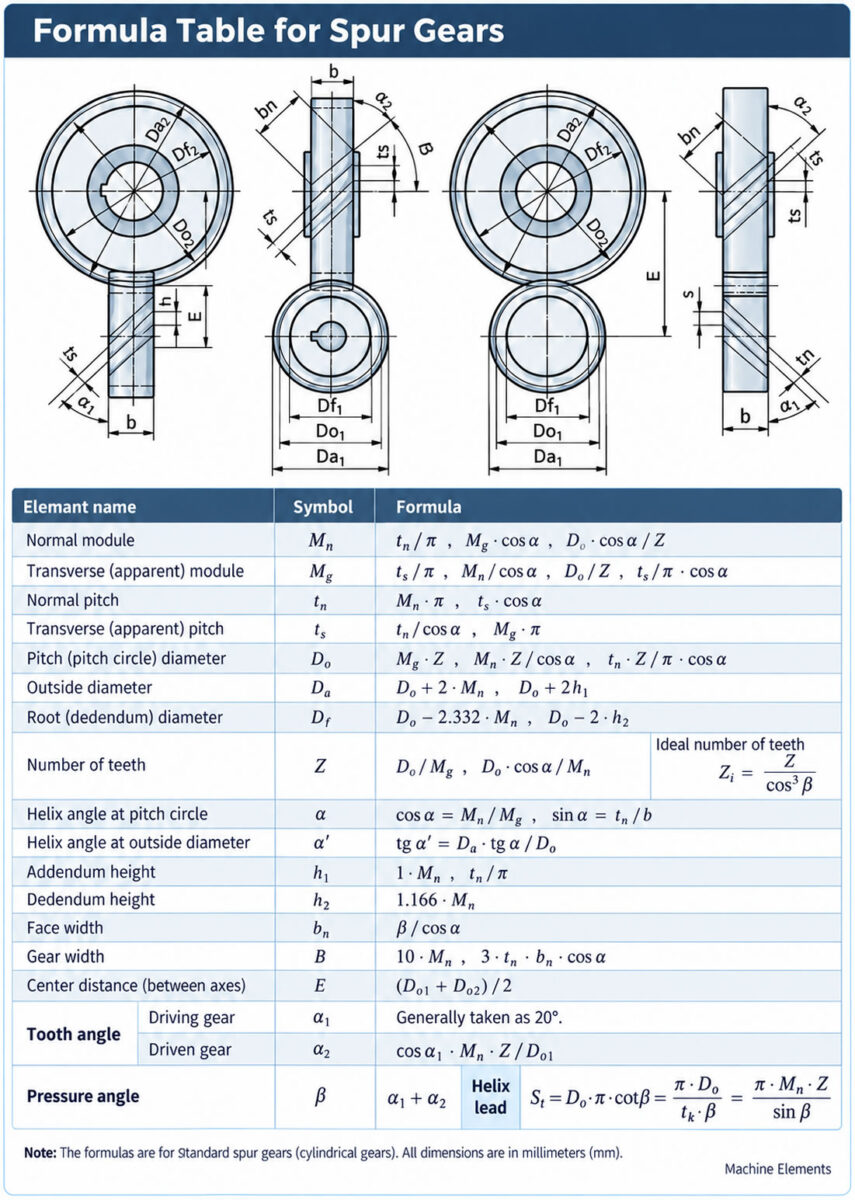

Elements of a Helical Gear
Because helical gears are cut at an angle, as shown in the figure below, when the gear is viewed from the front, the transverse module (Mg) and transverse pitch (ts) are what’s visible. When viewed perpendicular to the teeth, the normal module (Mn) and normal pitch (tn) are what’s seen. The helix angle (β) is generally 20°. When cutting a helical gear, the normal module (Mn) is used.

The dimensions and terms needed in manufacturing drawings of helical gears. The elements of a helical gear. The helix angle is generally around an average of 20°. The helix direction here is left-handed. When the axis is held perpendicular to the ground, if the angle leans to the left it’s called left-hand helix, if it leans to the right it’s called right-hand helix
Calculating Helical Gear Elements
Sample problem:
A cylindrical helical gear has a turned diameter (Da) of 140.18 mm, a tooth count of 42, and a helix angle of 20°. Find the values of the required elements of the cylindrical helical gear. (Mn, Mg, Da, Do, Df, b)

In this article, we covered the definition of and information about helical gears. Finding the helix direction on helical gears. The difference between helical gears and spur gears. The advantages of helical gears. Where helical gears are used. The elements and formulas of a helical gear. Calculating helical gear elements. See you in future articles.
Angled Tooth Structure
Helical gears have teeth angled relative to the shaft axis, and run more quietly than spur gears.
Progressive Tooth Contact
Thanks to the helix angle, the teeth engage gradually instead of all at once, reducing impact load.
Generation of Axial Force
The angled structure of helical gears generates an additional axial force on the shaft, which is generally counteracted with special thrust bearings.
Related Questions
In spur gears, a pair of teeth suddenly makes full contact and then suddenly separates, while in helical gears, this contact starts and ends gradually thanks to the angled tooth structure. This smooth transition eliminates the sudden-impact effect seen in spur gears, reducing noise.
The angled tooth structure, unlike spur gears, allows the gears to mesh and work together not only on parallel axes, but also on shafts positioned at specific angles. This flexibility makes helical gears usable in a wider range of mechanical layouts.
Related Posts