Close Menu
  • MAKİNELER ve İMALAT
    • Tools & Equipment
    • Computer-Aided Drawing
    • CAD/CAM Education
    • CNC Machine Programming
    • Casting Technologies
    • Electrical & Electronics Technologies
    • Hydraulics & Pneumatics
    • Manufacturing Processes
    • Manufacturing Technologies
    • Occupational Safety
    • Mold & Die Design
    • Solid Modeling
    • Welding Technology
    • Machine Elements
    • Mechanical Trade Drawing
    • Materials Science
    • Automotive & Vehicle Technologies
    • Robotics Technologies
    • Health Technologies
    • Defense & Aerospace Technologies
    • Descriptive Geometry
    • Technical Drawing
    • Software & Hardware Technologies
    • Innovative Manufacturing Methods
  • TEKNOLOJİ ve YAŞAM
    • OTOMOBİLLER ve TAŞIT
      • Vehicle & Engine Knowledge
      • Safe Driving
      • Sürüş Destek Sistemleri
    • Genel Kültür
      • Movies & TV Shows
      • Görsel ve Grafik Sanat
      • Books & Literature
      • Music
      • Sports
      • History
      • History of Technology
    • GÜNDELİK YAŞAM TEKNOLOJİLERİ
    • Hobbies & Entertainment
    • Internet Technologies
    • Health
    • Mobile Technologies
Makine Eğitimi
  • Machines & Manufacturing
    Machine Elements
    Hydraulics & Pneumatics
    Technical Drawing
    Computer-Aided Design & Manufacturing
    Basic Manufacturing Processes
    Manufacturing Processes
    Industry Technologies
    Other Technical Courses
    Motion & Power Transmission
    Simple Machines
    Chains & Sprockets
    Shafts & Journals
    Gears
    Cams
    Couplings
    Belts & Pulleys
    Springs
    Bearings
    Keys
    Fastening Joining
    Retaining Rings
    Screws, Bolts & Nuts
    Cotter Pins
    Flanges
    Welding
    Rivets
    Pins & Bolts
    Washers
    Calculators
    Gear Ratio Calculator
    Spring Constant Calculator
    Belt Pulley Ratio Calculator
    Other Machine Elements
    Slides & Linear Guides
    Brakes
    Flywheels
    Clamps
    Shock Absorbers
    Gaskets & O-Rings
    Seals & Sealing Elements
    Hydraulics
    Introduction to Hydraulics & Principles
    Hydraulic Systems & Applications
    Accumulators
    Filters
    Motors
    Pumps
    Valves
    Pneumatics
    Introduction to Pneumatics & Principles
    Pneumatic Systems & Applications
    Pneumatic Circuit Components
    Valves
    Cylinders
    Silencers
    Motors
    Compressors
    Dryers
    Conditioning Units
    Common Topics & Maintenance
    Hydraulic & Pneumatic Maintenance
    Study Notes, Exams & Tests
    Technical Drawing
    Introduction to Technical Drawing
    Geometric Drawings
    Perspective & Projection
    Orthographic Views
    Dimensioning
    Sectioning
    Assembly & Detail Drawings
    Tolerances
    Surface Finish Symbols
    Mechanical Engineering Drawing
    Screws, Bolts & Nuts
    Pulley Drawings
    Gear Drawings
    Shafts & Journals
    Bearing Drawings
    Pins & Bolts
    Spring Drawings
    Welds in Technical Drawing
    Washers
    Cotter Pins
    Technical Drawing Exercises
    Mechanical Drawing Exercises
    Gear Exercises
    View Extraction Exercises
    Pulley Exercises
    Pin & Bolt Exercises
    Threaded Fastening Exercises
    Descriptive Geometry
    Computer-Aided Drawing
    AutoCAD Drawing Lessons
    Computer-Aided Drawing Exams
    Solid Modeling & Animation
    Solid Model Drawing Files
    Solid Model Assembly Examples
    Solid Model Drawing Lessons
    3D CAD Software Reviews
    Solid Modeling Exercises
    CNC Programming
    CAM
    Measurement & Inspection
    Dial Indicators
    Calipers
    Gauges
    Micrometers
    Materials Science
    Steels
    Cast Iron
    Aluminum
    Plastics
    Material Testing & Hardness Measurement
    Occupational Safety
    Workshop Safety
    Safety When Working With Electricity
    Machine Safety Rules
    Hand Operations
    Filing
    Marking
    Cutting Operations
    Reaming
    Tapping
    Threading With a Die
    Drill Bit Sharpening
    Working With Machines
    Basic Turning Operations
    Basic Milling Operations
    Shaper Machine
    Machining
    Turning
    Milling
    Grinding
    Innovative Manufacturing Methods
    EDM (Electrical Discharge Machining)
    Laser Machining
    Waterjet Machining
    3D Printing
    3D Scanners
    Welding
    Rolling
    Casting
    Mold & Die Design
    Mechanical & Hydraulic Presses
    Blanking & Piercing Dies
    Bending Dies
    Drawing Dies
    Plastic Injection Molds
    Extrusion Dies
    Compound Dies
    Progressive Dies
    Blow Molds
    Spinning Dies
    Spray Molds
    Manufacturing of Machine Parts
    Automotive & Vehicle Technologies
    Motor Vehicle Manufacturing
    Raw Material Production
    History of Technology
    Health & Medical Technologies
    Defense & Aerospace
    Robotics Technologies
    Software & Hardware Technologies
    Mechanics - Strength of Materials
    Physics Topics
  • Technology & Life
    Hobbies & Entertainment
    Sports
    Music
    Vehicle & Engine Knowledge
    Vehicle Maintenance & Repair
    Safe Driving
    Driver Assistance Systems
    History
    Movies & TV Shows
    Books & Literature
    Computers & Internet
    Computer Tips
    Software Reviews
    Hardware & Peripherals
    Practical & Safe Internet Use
    Visual & Graphic Art
    Mobile Technologies
    Travel
    Science
    Health
    First Aid Knowledge
    Everyday Technologies
Makine Eğitimi
Home»Machine Elements»Dimensional Tolerances – Annotated Example Drawings
29 August 2026

Dimensional Tolerances – Annotated Example Drawings

Dimensional Tolerances Annotated Example Drawings

Example 1 – Motion Transmission Through Flanges

Two shafts are joined by flanges to transmit motion from one shaft to the other (the flanges are shown in green and blue.)

  • Example 1 – Motion Transmission Through Flanges
  • Example 2 – Assembly Drawing of a Pulley Mounted on a Supported Shaft
  • Related Questions

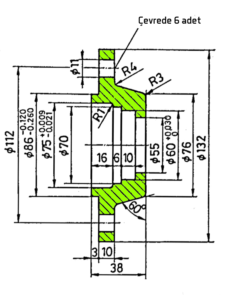
The flanges are fastened to the shafts with a key and a bolt-and-nut. They are joined to each other by a male-female fit. The green one has a recess, the blue one has a matching protrusion.

A gear (orange), keyed onto the stepped shaft (Shaft 2) and located axially by a spacer collar (yellow), is also present.

dimensional tolerance example drawings technical drawing

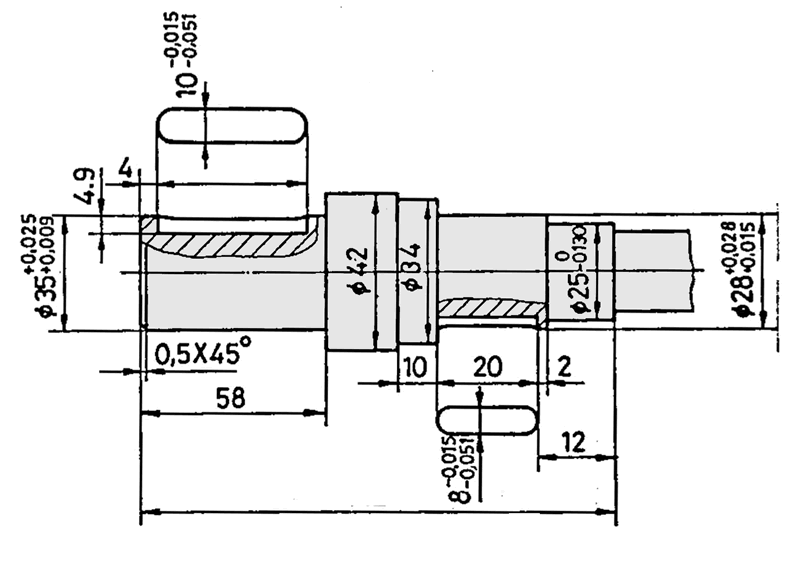
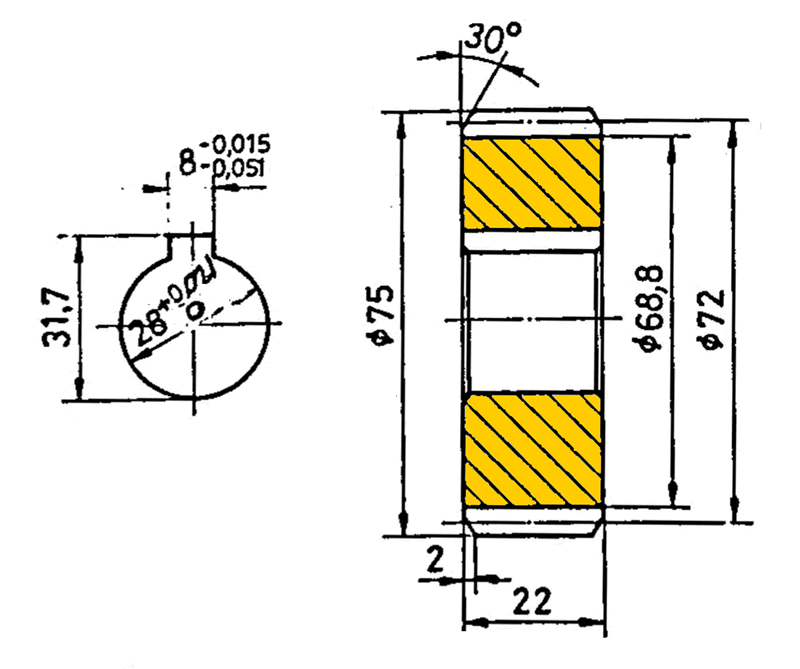
In the example, the tolerance grades are first determined according to the type of fit, and the upper and lower deviations corresponding to each grade are written numerically in their place on the detail drawings.

flange, gear, key, shaft, bolt, nut assembly technical drawing
  • Flange 1 – Shaft 1 = Close-fit transition fit (H7/k6)
  • Flange 1 – Flange 2 = (male-female flanges) Medium-fit clearance fit (H8/c11)
  • Flange 1 keyway width = P9 (per TS 147)
  • Flange 2 – Shaft 2 = Close-fit press fit (H7/m6)
  • Flange 2 and gear keyway width = P9 (per TS 147)
  • Gear – Shaft 2 = Close-fit tight fit (H7/n6)
  • Keyway widths on the shaft = P9 (per TS 147)
  • Spacer collar – Shaft 2 = (shown in yellow) Coarse-fit coarse clearance fit-1 (H11/h11)
flange manufacturing drawing with tolerances
FLANGE 1
flange technical drawing with tolerances
FLANGE 2
shaft
SHAFT 1
stepped shaft keyway tolerance
SHAFT 2
gear technical drawing
GEAR
spacer collar technical drawing section hatching
SPACER COLLAR

Dimensional Tolerance


In technical drawing, tolerance refers to the difference between the largest and smallest values a dimension is allowed to have.

IT Quality Grades


The ISO tolerance system standardizes the level of precision with quality grades ranging from IT01 to IT18.

Fit Tolerances


In supported shaft-hub connections, whether the fit is a clearance, transition, or interference fit is determined by how the tolerances are positioned relative to each other.

Example 2 – Assembly Drawing of a Pulley Mounted on a Supported Shaft

A belt pulley assembled onto a supported stepped shaft. Parts used in the assembly: bearing, oil seal, washer, hex nut, bolt, castellated nut, cotter pin, key.

  • Cover – Housing =
    Medium-fit clearance fit (H8 / d10)
  • Cover – Bearing =
    K7 (from the bearing catalog)
  • Shaft – Bearing =
    k6 (from the bearing catalog)
  • Oil seal bore =
    H7 (from the oil seal catalog)
  • Pulley – Shaft =
    Close-fit transition fit (H7 / k6)
  • Pulley keyway width =
    Js9 (per TS 147)
  • Shaft keyway width = N9 (per TS 147)
pulley assembly mounted on a supported shaft, bearing, washer, castellated nut, cotter pin
ASSEMBLY DRAWING
bearing housing technical drawing dimensioning, internal thread, hatching
HOUSING
cover technical drawing
COVER
stepped shaft technical drawing dimensioning keyway, partial section, tolerance, hatching
STEPPED SHAFT
belt pulley technical drawing dimensioning, full section
BELT PULLEY

Related Questions

The uppercase letter (H) indicates the hole’s tolerance class, and the lowercase letter (k) indicates the shaft’s tolerance class; the numbers indicate how precise that class is. This combination defines how tightly the two parts will fit together.

This depends on the part’s function. A part that transmits torque, like a gear, needs a tight fit to the shaft, while a collar that needs to be removed and reinstalled is designed with a looser fit.

Related Posts

Gear Terminology and Elements Gear Terminology – Gear Elements Spur, Helical, and Bevel Gear Cutting Exercises Spur, Helical, and Bevel Gear Cutting Exercises Gear Calculation Formula Tables Gear Calculation Formulas Table Pins and Pinned Joint Technical Drawings Pins and Pinned Joint Technical Drawings Gear Mechanism Assembly and Detail Drawing Gear Mechanism Assembly and Detail Drawing AutoCAD Example Complex Drawings AutoCAD Example Drawings 2 – Complex Drawings Teknik Resimde Yataklar Rulmanlar Bearings in Technical Drawing Nut Drawing and Dimension Tables Nut Drawing and Dimension Tables
Flanges Tolerances in Technical Drawing
Share. Facebook Twitter WhatsApp Tumblr Email Telegram Copy Link

Leave A Reply Cancel Reply


How to Jump-Start a Battery, Illustrated
Why Is It Dangerous to Rest Your Feet on the Dashboard?
  • Contact
  • Terms of Service
  • Privacy & Cookie Policy

Type above and press Enter to search. Press Esc to cancel.