
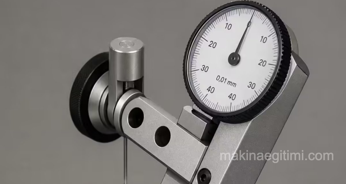
In this article we will cover the types of dial indicators. We can classify dial indicators by their precision, by their type, and by the areas in which they are used.
Types of dial indicators by precision
0.01 mm precision dial indicator:
Metric dial indicators generally have a precision of 0.01 mm.
0.001 mm precision dial indicator:
On this dial indicator, the graduations are arranged according to 1 µm (micrometre) = 0.001 mm.
0.0001 mm precision dial indicator (electronic dial indicator):
These dial indicators have an electronic system and have either a needle or a digital display.
The dial indicator’s operating method is based on converting an electric current into a unit of length.
When the device’s probe tip moves according to the dimensional deviations on the surface of the workpiece, the iron core inside slides within the induction coil. This creates a change in the alternating-current induction voltage. This change is amplified, converted to direct current, and read out in units of length.

how to use an electronic dial indicator
Micron Precision
Dial indicators can generally measure with a precision ranging from 0.01 mm down to 0.001 mm.
Digital Dial Indicator Advantage
Digital dial indicators offer faster, error-free reading compared to analog needle-type models.
Prevalence of Dial-Face Models
Dial-face (clock-type) dial indicators are still widely used in the workshop because they can operate without electricity.
Types of dial indicators by type
Analog dial indicators
These are dial indicators that work with a mechanical system and are known as clock-type (dial-face) indicators.
Digital dial indicators
These dial indicators are used in the same way as analog dial indicators. The single, most important difference is that these dial indicators have no dial face, needle, or graduations. They are available in 0.01 mm and 0.001 mm precision.
Types of dial indicators by area of use
- Outside diameter dial indicator,
- Inside diameter dial indicator,
- Pipe (tube) dial indicator,
- Thickness dial indicator,
- Depth dial indicator,
- Groove dial indicator,
- Thread dial indicator,
- Runout (test) dial indicator
Groove dial indicator

It is used to check the diameters of grooves cut inside cylindrical bores. On groove dial indicators, one of the jaws can be adjusted to open and close.
The dial indicator is then set according to the nominal diameter of the groove to be checked. The figure below shows a digital groove dial indicator

Outside diameter dial indicator
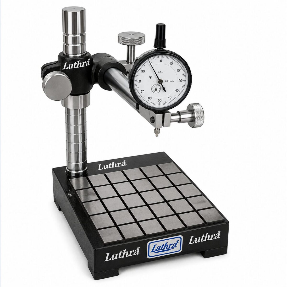
Outside diameter dial indicators are mounted on a stand so that the indicator can move vertically along the column. They are used to check outside diameters and heights. The figure above shows the dial indicator and its stand used for checking outside diameters.
Inside diameter dial indicator
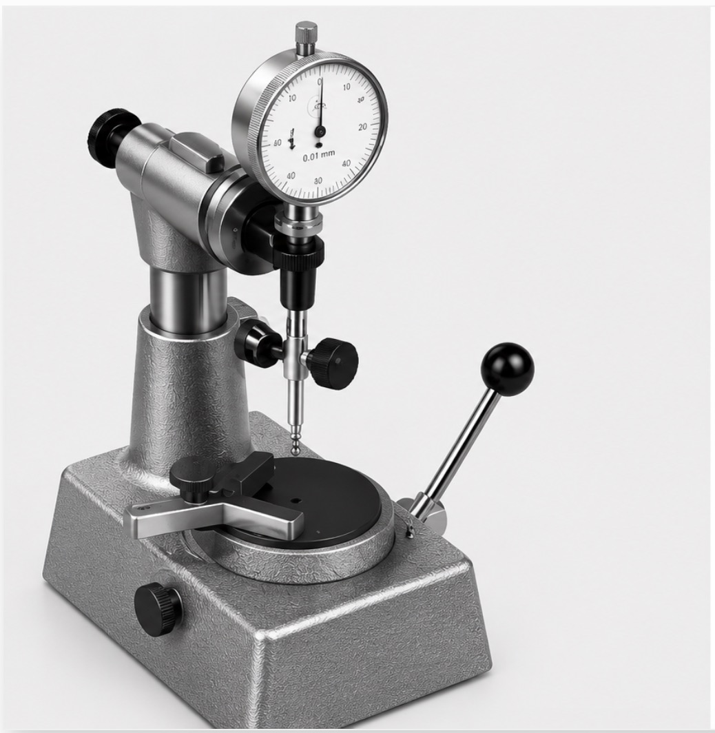
Inside diameter dial indicators are divided into two groups according to small and large bore diameters. For checking small diameters, caliper-tip inside diameter dial indicators are used, and for checking large-diameter bores, three-point centering dial indicators are used. Both types of inside diameter dial indicators are first set to the nominal size using ring gauges.

Thickness dial indicator
These types of dial indicators are generally used to check parts of a certain thickness. The thickness of small parts is checked with the pocket-type thickness dial indicators shown below.

pocket-type analog thickness dial indicator

pocket-type digital thickness dial indicator
Depth dial indicator

Depth dial indicators are used to check cylindrical bore and groove depths, heights, and similar dimensions. This type of dial indicator has interchangeable, insertable measuring rods. A rod matching the nominal depth is fitted to the tip of the indicator’s measuring spindle.
Pipe (Tube) Dial Indicator

Pipe dial indicators are used to check pipe wall thicknesses. The fixed jaw of the pipe dial indicator is interchangeable and sized according to the pipe’s inside diameter. A fixed jaw matching the inside diameter of the pipe whose wall thickness is to be checked is selected and screwed into its socket. The figure below shows a pocket-type pipe dial indicator.
Thread dial indicator
It is used to check the pitch diameter and root diameter of internal and external threads. Just as with the groove dial indicator, the thread dial indicator also has a jaw that can be adjusted for internal and external thread diameters. Anvils matching the thread profile are fitted to the tips of both the adjustable jaw and the jaw that contacts the indicator. The dial indicator is first set using a gauge selected according to the thread type. Then the dimensional check is performed.
Runout dial indicator (lever-type dial indicator)
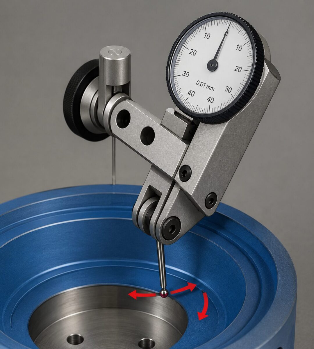
For accurate measurement, when measuring with a runout (lever-type) dial indicator, the axis of the measuring tip must be parallel to the part being measured or the measuring plate, as shown in the picture below, or must form as narrow an angle with the surface as possible.

These dial indicators can be used for different measurements thanks to their pivoting (lever-type) measuring tip. Example: used for checking cylindricity runout on rotating parts, and for aligning and centering internal parts.
Related Questions
Electronic dial indicators convert small movements into an electrical signal and amplify it; this provides a precision beyond the limits of mechanical gear systems. This makes it possible to detect much finer measurement differences, such as 0.0001 mm.
No, the measurement precision should be chosen according to the tolerance required by the job. Using an overly precise dial indicator for a rough check leads to unnecessary cost and wasted time.
Related Posts
 Measurement and Inspection on the Lathe
 Vernier Caliper Simulator
 What Is a Dial Indicator? How to Use It
 1/10 1/20 1/50 Caliper Reading Practice Questions
 How to Read a Caliper. Caliper Reading Explained
 What Is a Gauge. Why Is It Used?
 Micrometers. Parts, Types, and Maintenance of a Micrometer
 Micrometer Simulator