
Close Menu
  • MAKİNELER ve İMALAT
    • Tools & Equipment
    • Computer-Aided Drawing
    • CAD/CAM Education
    • CNC Machine Programming
    • Casting Technologies
    • Electrical & Electronics Technologies
    • Hydraulics & Pneumatics
    • Manufacturing Processes
    • Manufacturing Technologies
    • Occupational Safety
    • Mold & Die Design
    • Solid Modeling
    • Welding Technology
    • Machine Elements
    • Mechanical Trade Drawing
    • Materials Science
    • Automotive & Vehicle Technologies
    • Robotics Technologies
    • Health Technologies
    • Defense & Aerospace Technologies
    • Descriptive Geometry
    • Technical Drawing
    • Software & Hardware Technologies
    • Innovative Manufacturing Methods
  • TEKNOLOJİ ve YAŞAM
    • OTOMOBİLLER ve TAŞIT
      • Vehicle & Engine Knowledge
      • Safe Driving
      • Sürüş Destek Sistemleri
    • Genel Kültür
      • Movies & TV Shows
      • Görsel ve Grafik Sanat
      • Books & Literature
      • Music
      • Sports
      • History
      • History of Technology
    • GÜNDELİK YAŞAM TEKNOLOJİLERİ
    • Hobbies & Entertainment
    • Internet Technologies
    • Health
    • Mobile Technologies
Makine Eğitimi
  • Machines & Manufacturing
    Machine Elements
    Hydraulics & Pneumatics
    Technical Drawing
    Computer-Aided Design & Manufacturing
    Basic Manufacturing Processes
    Manufacturing Processes
    Industry Technologies
    Other Technical Courses
    Motion & Power Transmission
    Simple Machines
    Chains & Sprockets
    Shafts & Journals
    Gears
    Cams
    Couplings
    Belts & Pulleys
    Springs
    Bearings
    Keys
    Fastening Joining
    Retaining Rings
    Screws, Bolts & Nuts
    Cotter Pins
    Flanges
    Welding
    Rivets
    Pins & Bolts
    Washers
    Calculators
    Gear Ratio Calculator
    Spring Constant Calculator
    Belt Pulley Ratio Calculator
    Other Machine Elements
    Slides & Linear Guides
    Brakes
    Flywheels
    Clamps
    Shock Absorbers
    Gaskets & O-Rings
    Seals & Sealing Elements
    Hydraulics
    Introduction to Hydraulics & Principles
    Hydraulic Systems & Applications
    Accumulators
    Filters
    Motors
    Pumps
    Valves
    Pneumatics
    Introduction to Pneumatics & Principles
    Pneumatic Systems & Applications
    Pneumatic Circuit Components
    Valves
    Cylinders
    Silencers
    Motors
    Compressors
    Dryers
    Conditioning Units
    Common Topics & Maintenance
    Hydraulic & Pneumatic Maintenance
    Study Notes, Exams & Tests
    Technical Drawing
    Introduction to Technical Drawing
    Geometric Drawings
    Perspective & Projection
    Orthographic Views
    Dimensioning
    Sectioning
    Assembly & Detail Drawings
    Tolerances
    Surface Finish Symbols
    Mechanical Engineering Drawing
    Screws, Bolts & Nuts
    Pulley Drawings
    Gear Drawings
    Shafts & Journals
    Bearing Drawings
    Pins & Bolts
    Spring Drawings
    Welds in Technical Drawing
    Washers
    Cotter Pins
    Technical Drawing Exercises
    Mechanical Drawing Exercises
    Gear Exercises
    View Extraction Exercises
    Pulley Exercises
    Pin & Bolt Exercises
    Threaded Fastening Exercises
    Descriptive Geometry
    Computer-Aided Drawing
    AutoCAD Drawing Lessons
    Computer-Aided Drawing Exams
    Solid Modeling & Animation
    Solid Model Drawing Files
    Solid Model Assembly Examples
    Solid Model Drawing Lessons
    3D CAD Software Reviews
    Solid Modeling Exercises
    CNC Programming
    CAM
    Measurement & Inspection
    Dial Indicators
    Calipers
    Gauges
    Micrometers
    Materials Science
    Steels
    Cast Iron
    Aluminum
    Plastics
    Material Testing & Hardness Measurement
    Occupational Safety
    Workshop Safety
    Safety When Working With Electricity
    Machine Safety Rules
    Hand Operations
    Filing
    Marking
    Cutting Operations
    Reaming
    Tapping
    Threading With a Die
    Drill Bit Sharpening
    Working With Machines
    Basic Turning Operations
    Basic Milling Operations
    Shaper Machine
    Machining
    Turning
    Milling
    Grinding
    Innovative Manufacturing Methods
    EDM (Electrical Discharge Machining)
    Laser Machining
    Waterjet Machining
    3D Printing
    3D Scanners
    Welding
    Rolling
    Casting
    Mold & Die Design
    Mechanical & Hydraulic Presses
    Blanking & Piercing Dies
    Bending Dies
    Drawing Dies
    Plastic Injection Molds
    Extrusion Dies
    Compound Dies
    Progressive Dies
    Blow Molds
    Spinning Dies
    Spray Molds
    Manufacturing of Machine Parts
    Automotive & Vehicle Technologies
    Motor Vehicle Manufacturing
    Raw Material Production
    History of Technology
    Health & Medical Technologies
    Defense & Aerospace
    Robotics Technologies
    Software & Hardware Technologies
    Mechanics - Strength of Materials
    Physics Topics
  • Technology & Life
    Hobbies & Entertainment
    Sports
    Music
    Vehicle & Engine Knowledge
    Vehicle Maintenance & Repair
    Safe Driving
    Driver Assistance Systems
    History
    Movies & TV Shows
    Books & Literature
    Computers & Internet
    Computer Tips
    Software Reviews
    Hardware & Peripherals
    Practical & Safe Internet Use
    Visual & Graphic Art
    Mobile Technologies
    Travel
    Science
    Health
    First Aid Knowledge
    Everyday Technologies
Makine Eğitimi
Home»Manufacturing Processes»Milling and Slotting with an End Mill
29 August 2026

Milling and Slotting with an End Mill

Milling and Slotting with an End Mill

End mills are made in a wide variety of types. We can attribute this to how many different places they’re used on machines and parts in industry. End mills are used to do work in various positions in the vertical heads of universal milling machines. These tools are held either directly in the spindle socket or in the head’s collets, using collet chucks.

  • Milling with an End Mill
    • Points to Pay Attention to When Milling with an End Mill
  • Slotting with an End Mill
    • Zeroing When Slotting with an End Mill

Milling with an End Mill

There are also indexable-insert end mills. Because of their profile, end mills are generally used for operations like pocket milling and slotting.
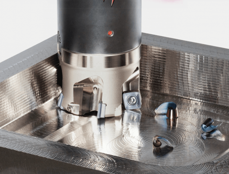
pocket milling with an indexable-insert end mill

When people think of end mills, cutting keyways in shafts usually comes to mind, but they’re also used for various other milling operations. For example, machining die components, drilling and enlarging holes, and hollowing out interior sections (pocket milling).

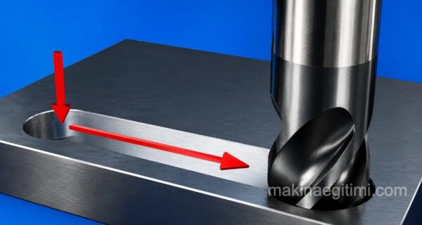
vertical-feed slotting with an end mill

The image above shows a clamping-shoe slot being hollowed out with an end mill.

angled milling with an end mill

In the image above, a helical-flute, multi-tooth end mill that cuts on both the face and the periphery has been mounted in the machine’s universal head socket using a draw-in bar. However, it’s been rotated at an angle from the head, appropriate for the machining inside the hole. The workpiece is clamped to the table with a clamping shoe, packing block, and bolts, and a slot, or a pocket according to a drawing, is being machined inside it.

end mill machining CAD/CAM shoe sole mold

Above is an example of end-mill machining on a multi-axis vertical CNC machining center using CAD/CAM. End mills are used a great deal, especially in mold making, to machine pockets and detail surfaces.

Points to Pay Attention to When Milling with an End Mill

1 — The tip of the end mill must not be crashed into the workpiece while positioning it. It can break or run out.

2 — The clamping method should be chosen to match the shank’s shape.

3 — Unlike a drill, the tip of an end mill can’t feed along its own axis. It can only plunge by a limited amount.

4 — Since these cutters mostly cut with their side surfaces, their tips wear quickly. The worn amount can be reground on the face, but only peripheral, surface cuts should then be taken.

5 — On end mills, deep cuts that could flex the teeth where they join the shank should not be taken.

6 — In general, multi-tooth end mills with helical or straight flutes are used for milling surfaces, while 2-, 3-, and 4-tooth end mills are used for cutting various slots and for drilling operations that feed along a fixed axis.

Since these cutters, used for various cutting operations, are known to dull quickly, the explanations above should be followed carefully.

Slotting with an End Mill

slotting with an end mill

When cutting keyways in shafts, it’s important to take the necessary care while using end mills. Otherwise, this rather expensive cutter can naturally be destroyed in an instant.

slot milling with an end mill

To illustrate this, pay attention to the explanations below.

The shaft is marked along its axis according to the type of keyway to be cut on it — that is, whether it’s open at one end or closed at both ends.

The workpiece is clamped in the vise or on the table with special clamping tools. If the shaft is being mounted on the table, the table is seated lengthwise in the “T” slots; if that’s not possible, it should be mounted on V-blocks, using clamps and bolts. The same shaft can, in a different setup, be mounted with a three-jaw universal chuck and a center, or directly between two centers.

Zeroing When Slotting with an End Mill

how is zeroing done when milling with an end mill

As shown at the side, the milling cutter is brought up to the side of the workpiece. With a piece of paper placed between them, the table is brought closer with the carriage until the paper tears. When it starts to tear, the cross-feed micrometer collar is set to zero. After setting the cutter’s side surface, the table is lowered from the knee.

For example;

If the end mill’s diameter is 12 mm and the workpiece’s diameter is 30 mm, since the paper’s thickness is 0.025 mm (which can be ignored), when the paper tears, the table’s position is,

12/2 + 30/2 + 0.025 =
6+ 15 + 0.025= 21.025 mm. The table is advanced this much from the micrometer collar.

The end mill can also be set to the workpiece’s axis using other methods, but
the method above is the most convenient.

setting the milling cutter to the workpiece axis

Setting the end mill to the shaft’s axis when milling with an end mill is shown separately in the drawings above.

Set from the side surface, the cutter is brought onto the workpiece’s axis as shown above; here, zeroing is done so it’s tangent to the shaft, and the desired depth is then given.

The keyway is then cut using the appropriate cutting speed and feed for the end mill. If both ends of the slot are closed, a “two-flute” end mill should be chosen here. But if a multi-tooth end mill is going to be used, a hole of the appropriate depth should first be drilled at each end of the slot. This is because multi-tooth end mills can’t feed along their own axis — they’ll break.

slotting with an end mill

At the end of the operation, it’s measured, checked, and cleaned up.
If the ends of the keyway are open, a cutter thin enough to enter from outside the part — a slot mill — can be used; or if the shaft diameter is large, small-diameter “T” slot cutters can also be used.

Related Posts
Balancing a Grinding Wheel Balancing a Grinding Wheel. Grinding Wheel Balancing Supporting a Workpiece on a Lathe Steady Rests on a Lathe. Supporting a Workpiece on a Lathe Drill presses and their types, title image Drill Presses and Their Types Workplace Safety with Hand Tools Workplace Safety and Misuse of Hand Tools Operations Performed on a Lathe Operations Performed on a Lathe Information about end mill cutters Information About End Mill Cutters How Is a Rivet Gun Used How Is a Rivet Gun Used Information About Module Milling Cutters Information About Module Milling Cutters
Milling kesici takımlar Basic Milling Operations
Share. Facebook Twitter WhatsApp Tumblr Email Telegram Copy Link

Leave A Reply Cancel Reply


Features and Advantages of LED Headlights
How Is Spark Plug Cleaning Done. Ways to Clean Spark Plugs
  • Contact
  • Terms of Service
  • Privacy & Cookie Policy

Type above and press Enter to search. Press Esc to cancel.