Close Menu
  • MAKİNELER ve İMALAT
    • Tools & Equipment
    • Computer-Aided Drawing
    • CAD/CAM Education
    • CNC Machine Programming
    • Casting Technologies
    • Electrical & Electronics Technologies
    • Hydraulics & Pneumatics
    • Manufacturing Processes
    • Manufacturing Technologies
    • Occupational Safety
    • Mold & Die Design
    • Solid Modeling
    • Welding Technology
    • Machine Elements
    • Mechanical Trade Drawing
    • Materials Science
    • Automotive & Vehicle Technologies
    • Robotics Technologies
    • Health Technologies
    • Defense & Aerospace Technologies
    • Descriptive Geometry
    • Technical Drawing
    • Software & Hardware Technologies
    • Innovative Manufacturing Methods
  • TEKNOLOJİ ve YAŞAM
    • OTOMOBİLLER ve TAŞIT
      • Vehicle & Engine Knowledge
      • Safe Driving
      • Sürüş Destek Sistemleri
    • Genel Kültür
      • Movies & TV Shows
      • Görsel ve Grafik Sanat
      • Books & Literature
      • Music
      • Sports
      • History
      • History of Technology
    • GÜNDELİK YAŞAM TEKNOLOJİLERİ
    • Hobbies & Entertainment
    • Internet Technologies
    • Health
    • Mobile Technologies
Makine Eğitimi
  • Machines & Manufacturing
    Machine Elements
    Hydraulics & Pneumatics
    Technical Drawing
    Computer-Aided Design & Manufacturing
    Basic Manufacturing Processes
    Manufacturing Processes
    Industry Technologies
    Other Technical Courses
    Motion & Power Transmission
    Simple Machines
    Chains & Sprockets
    Shafts & Journals
    Gears
    Cams
    Couplings
    Belts & Pulleys
    Springs
    Bearings
    Keys
    Fastening Joining
    Retaining Rings
    Screws, Bolts & Nuts
    Cotter Pins
    Flanges
    Welding
    Rivets
    Pins & Bolts
    Washers
    Calculators
    Gear Ratio Calculator
    Spring Constant Calculator
    Belt Pulley Ratio Calculator
    Other Machine Elements
    Slides & Linear Guides
    Brakes
    Flywheels
    Clamps
    Shock Absorbers
    Gaskets & O-Rings
    Seals & Sealing Elements
    Hydraulics
    Introduction to Hydraulics & Principles
    Hydraulic Systems & Applications
    Accumulators
    Filters
    Motors
    Pumps
    Valves
    Pneumatics
    Introduction to Pneumatics & Principles
    Pneumatic Systems & Applications
    Pneumatic Circuit Components
    Valves
    Cylinders
    Silencers
    Motors
    Compressors
    Dryers
    Conditioning Units
    Common Topics & Maintenance
    Hydraulic & Pneumatic Maintenance
    Study Notes, Exams & Tests
    Technical Drawing
    Introduction to Technical Drawing
    Geometric Drawings
    Perspective & Projection
    Orthographic Views
    Dimensioning
    Sectioning
    Assembly & Detail Drawings
    Tolerances
    Surface Finish Symbols
    Mechanical Engineering Drawing
    Screws, Bolts & Nuts
    Pulley Drawings
    Gear Drawings
    Shafts & Journals
    Bearing Drawings
    Pins & Bolts
    Spring Drawings
    Welds in Technical Drawing
    Washers
    Cotter Pins
    Technical Drawing Exercises
    Mechanical Drawing Exercises
    Gear Exercises
    View Extraction Exercises
    Pulley Exercises
    Pin & Bolt Exercises
    Threaded Fastening Exercises
    Descriptive Geometry
    Computer-Aided Drawing
    AutoCAD Drawing Lessons
    Solid Modeling & Animation
    Solid Model Drawing Files
    Solid Model Assembly Examples
    Solid Model Drawing Lessons
    3D CAD Software Reviews
    Solid Modeling Exercises
    CNC Programming
    CAM
    Measurement & Inspection
    Dial Indicators
    Calipers
    Gauges
    Micrometers
    Materials Science
    Steels
    Cast Iron
    Aluminum
    Plastics
    Material Testing & Hardness Measurement
    Occupational Safety
    Workshop Safety
    Safety When Working With Electricity
    Machine Safety Rules
    Hand Operations
    Filing
    Marking
    Cutting Operations
    Reaming
    Tapping
    Threading With a Die
    Drill Bit Sharpening
    Working With Machines
    Basic Turning Operations
    Basic Milling Operations
    Shaper Machine
    Machining
    Turning
    Milling
    Grinding
    Innovative Manufacturing Methods
    EDM (Electrical Discharge Machining)
    Laser Machining
    Waterjet Machining
    3D Printing
    3D Scanners
    Welding
    Rolling
    Casting
    Mold & Die Design
    Mechanical & Hydraulic Presses
    Blanking & Piercing Dies
    Bending Dies
    Drawing Dies
    Plastic Injection Molds
    Extrusion Dies
    Compound Dies
    Progressive Dies
    Blow Molds
    Spinning Dies
    Spray Molds
    Manufacturing of Machine Parts
    Automotive & Vehicle Technologies
    Motor Vehicle Manufacturing
    Raw Material Production
    History of Technology
    Health & Medical Technologies
    Defense & Aerospace
    Robotics Technologies
    Software & Hardware Technologies
    Mechanics - Strength of Materials
    Physics Topics
  • Technology & Life
    Hobbies & Entertainment
    Sports
    Music
    Vehicle & Engine Knowledge
    Vehicle Maintenance & Repair
    Safe Driving
    Driver Assistance Systems
    History
    Movies & TV Shows
    Books & Literature
    Computers & Internet
    Computer Tips
    Software Reviews
    Hardware & Peripherals
    Practical & Safe Internet Use
    Visual & Graphic Art
    Mobile Technologies
    Travel
    Science
    Health
    First Aid Knowledge
    Everyday Technologies
Makine Eğitimi
Home»Mold & Die Design»Drawing Defects in Drawing Dies and How to Resolve Them
30 August 2026

Drawing Defects in Drawing Dies and How to Resolve Them

Çekme Kalıplarında Çekme Hataları ve Giderilmesi

In this article on die-making, we’ll cover the main defects that occur when forming with drawing dies, their causes, and how to resolve them.

  • Main Drawing Defects
    • Wall Thickness Imbalance in the Drawn Cup
    • Scratching, Marring, and Nicking
    • Orange-Peel Texture (Roughening)
    • Earing (Projections)
    • Stretcher Strains (Marks)
    • Discoloration (Burning)
    • Wrinkling
    • Springback
  • Related Questions

Main Drawing Defects

Wrinkling, tearing, and similar defects are never acceptable in parts produced with drawing dies. The most commonly encountered drawing defects and their causes are explained below.

Wall Thickness Imbalance in the Drawn Cup

The part undergoing the drawing process is subjected to bending, compressive, and tensile stresses. This variation across the bending, compression, and tension zones cannot be fully explained. However, the change in the drawn shape’s wall thickness varies depending on the type of the cup material, the drawing depth, the drawing speed, the pressure plate (blank holder) force, the coefficient of friction between the female die and the drawn cup (the lubrication system), and the one-sided die clearance.

Wall thickness imbalance in drawn parts
Figure 1 – Wall thickness imbalance in drawn parts

Above, the change in wall thickness is shown for a cup drawn from 1 mm thick aluminum sheet material.

Scratching, Marring, and Nicking

During drawing, the sheet material rubs against the surface of the female die. This friction causes scratching, marring, or hard-to-remove nicking on the surface of the cup. To eliminate these types of defects, the die must be properly lubricated, kept clean, and any heat generated during drawing must be dissipated.
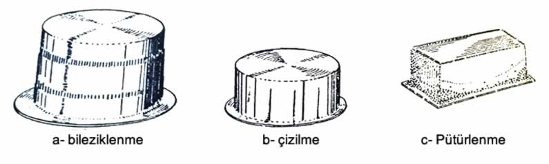
drawing defects roughening scratching
Figure 2 – Galling, scratching, and roughening on drawn parts

Orange-Peel Texture (Roughening)

A quality surface finish cannot be achieved when material grain coarsening occurs on the surface of the drawn cup. This results in a dull appearance on the drawn surface. To eliminate this type of defect, the formed part is polished with felt wheels, or the surface is chrome-plated.

Since this process increases the cost of the formed part, the part is instead tempered or subjected to a normalizing anneal. However, care must be taken during this process to prevent the drawn cup from tearing. Figure 2-c shows the roughening that occurs on the surface of a drawn cup.

Earing (Projections)

This is one of the defects frequently encountered in cups other than those made with flanged drawing. During drawing, the drawn shape elongates in the rolling direction of the material. This is because grain coarsening is greater in the rolling direction, and for cylindrical parts, the number of ears formed around the circumference varies according to this grain coarsening.

earing in parts drawn with drawing dies
Figure 3 – Earing on drawn parts

This defect is eliminated by using a larger initial blank diameter or dimensions, and trimming the mouth of the cup after drawing.

Stretcher Strains (Marks)

After drawing, patch-shaped streaks (marks) appear on the surface of the cup. These types of marks are called stretcher strains. Diagonal marks prevent the stress distribution on the surface of the drawn cup from being homogeneous. However, this type of drawing defect is generally minor.

Discoloration (Burning)

This type of defect frequently occurs in high-polish drawing operations. To eliminate this and similar defects, the one-sided die clearance is increased.

Wrinkling

Wrinkling can occur in the flange or body sections of the drawn cup material. These wrinkles are called material buildup and can cause the drawn cup to tear. To prevent wrinkling, the one-sided die clearance and the pressure plate (blank holder) force must be properly adjusted. Additionally, the die mouth and punch nose radius must be designed in a way that prevents wrinkling.

wrinkling in drawing dies

Springback

The cup exiting the drawing die opens up as a result of springback. To prevent this opening, the female die is tapered slightly inward starting from the mouth.

Besides these, many other drawing defects can occur, for example: the inability to perform a symmetrical drawing operation, the formation of tear zones at the mouth and base of flanged cups, corner tearing in rectangular or square drawing, and similar defects.


Tearing Defect


Excessive strain in drawing dies can cause tearing at the thinnest point of the material.

Wrinkling Problem


Insufficient pressure plate (blank holder) force can lead to wrinkling in the flange area of the material.

Springback


Some springback of the material after drawing is a common defect that must be compensated for in the die design.

Related Questions

The material is subjected to different stresses, such as bending, compression, and tension, in different regions during drawing. These different types of stress cause the cup’s wall thickness to vary from region to region.

The sheet material is shaped by rubbing against the surface of the female die during drawing. Insufficient lubrication or roughness on the die surface can cause scratches and marring on the part surface during this friction.

Related Posts
mounting of punches with cylindrical bodies and tips Mounting of Die Punches onto the Punch Plate Standard guide pillars Die Guide Pillars and Bushings Çekme Kalıbında Çekme Hızı ve Çekme Kuvveti Drawing Speed and Drawing Force in Drawing Dies Solidworks Kesme-hacim kalıbı tasarımları SolidWorks Mold Design: Blanking Die and Volume (Forming) Die Bending Force Calculation for Bending Dies Bending Force Calculation for Bending Dies Çekme kalıplarında Buruşma Önleme Preventing Wrinkling and Determining Draw Stages in Drawing Dies Mounting a die Mounting of Dies Parts of Eccentric Presses Parts of Eccentric Presses
Drawing Dies
Share. Facebook Twitter WhatsApp Tumblr Email Telegram Copy Link

Leave A Reply Cancel Reply

Is It Harmful to Drive Off Without Warming Up the Engine?
Causes and Symptoms of Catalytic Converter Failure
  • Contact
  • Terms of Service
  • Privacy & Cookie Policy

Type above and press Enter to search. Press Esc to cancel.