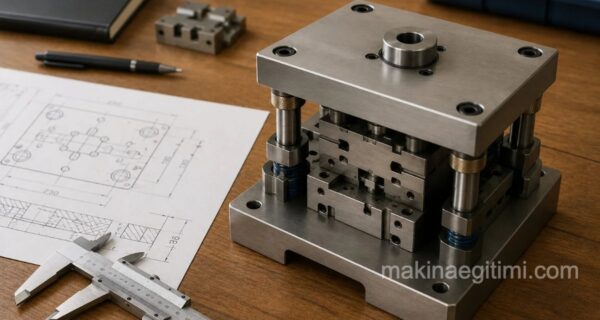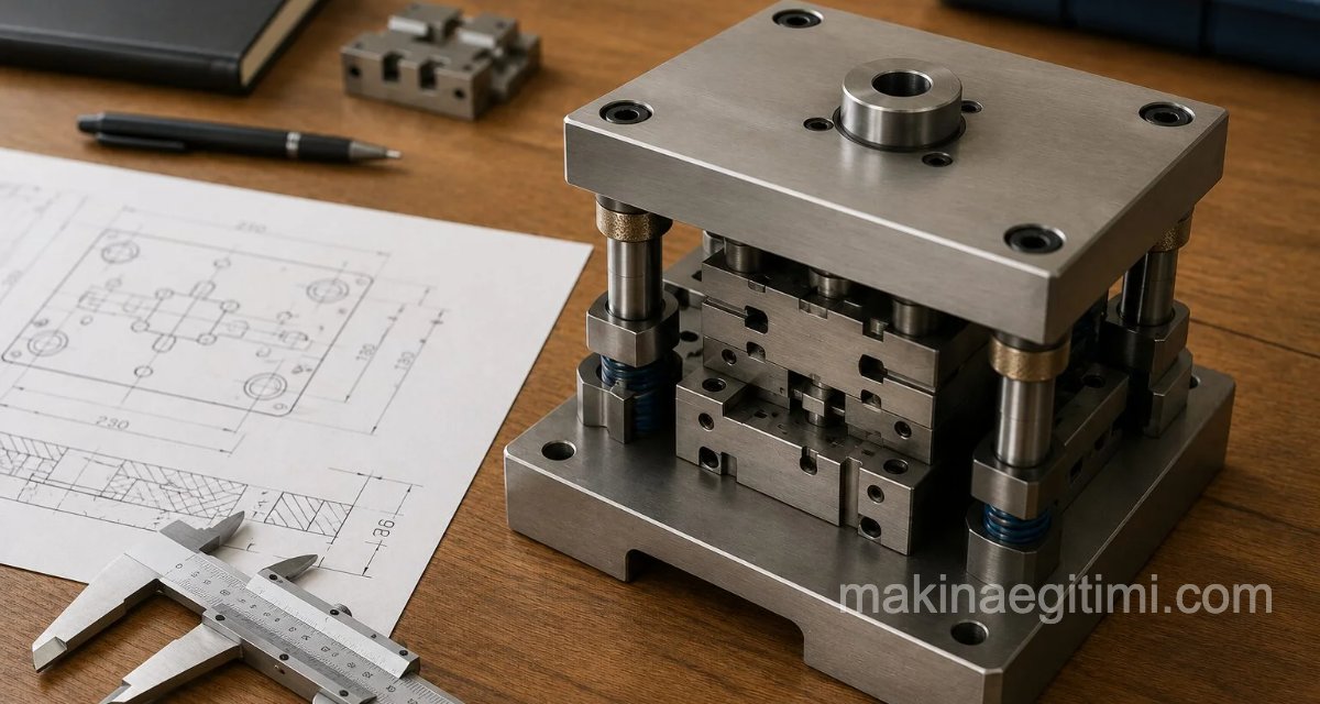
Guide pillars and bushings are among the components of a die set. Pillar-guided dies are generally used in dies that perform piercing, blanking, and similar forming operations with a small die cavity. The dimensional difference (tolerance) between the guide pillar and bushing used in these dies is important.
The tolerance between the guide pillar and bushing diameters is between a minimum of 0.0125 mm and a maximum of 0.0250 mm. Generally, the guide pillar diameter tolerance is taken as h3-h6, and the guide bushing bore tolerance is taken as H5.
For detailed information about tolerances, see: Hole and Shaft Tolerances and Tolerance Zone Selection and Practice Exercises
Characteristics of Guide Pillars and Bushings
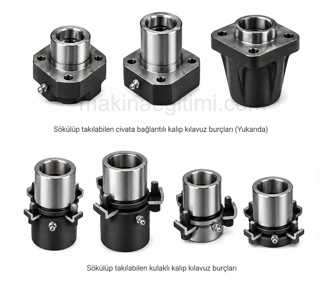
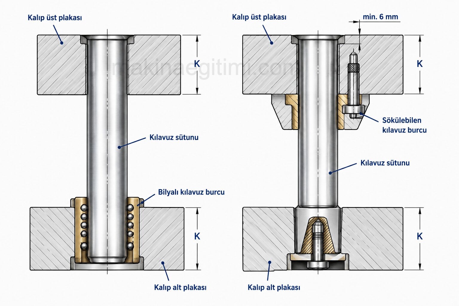
- How the guide pillars and bushings are mounted to the upper and lower die plates, and whether they can be removed and refitted during die construction or repair,
- For dies working with plain or shouldered cylindrical guide pillars and bushings, how the guide and bushing holes to be machined into the upper and lower die plates can be machined,
- The properties of the guide pillar and bushing materials used (for example, hardenable steels, bronze, chrome-plated, or bronze-plated steels),
- The lubrication method between the friction surfaces of the guide pillar and bushing,
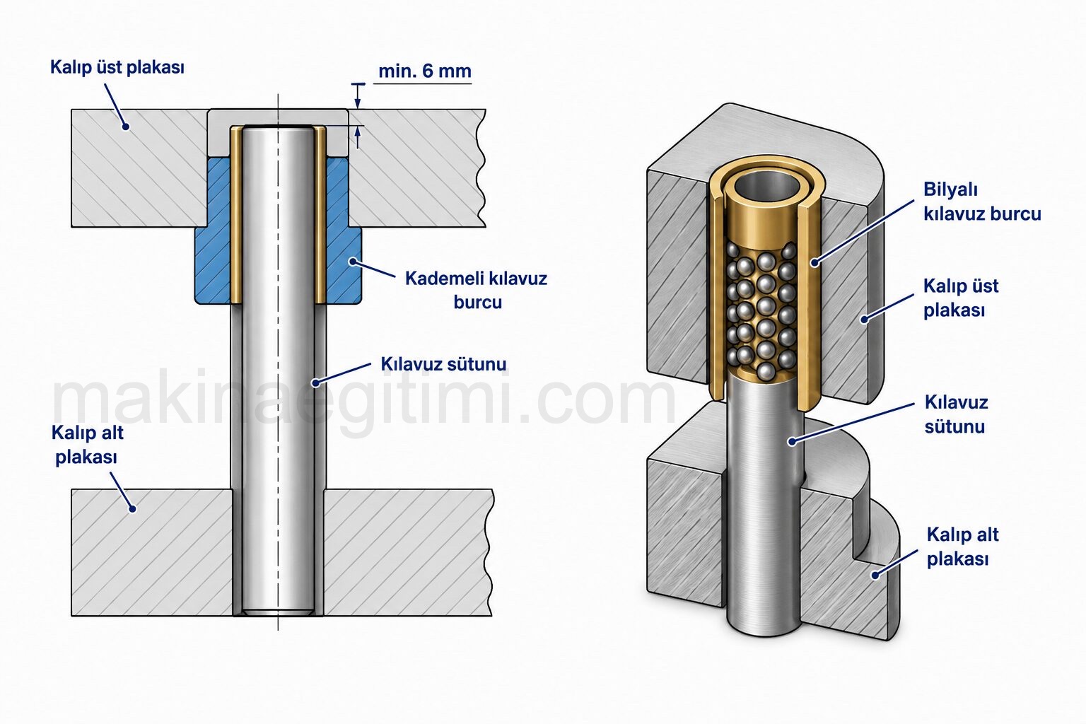
- Ball-bearing guide bushings and how they’re applied to the die
Certain points need to be considered depending on the location of use and characteristics like these.
Die Guide Pillars


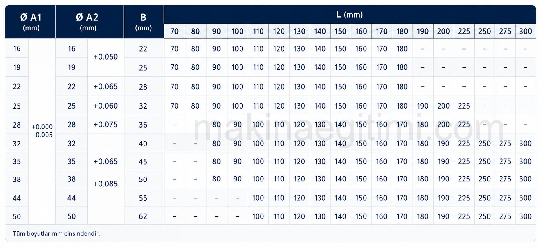
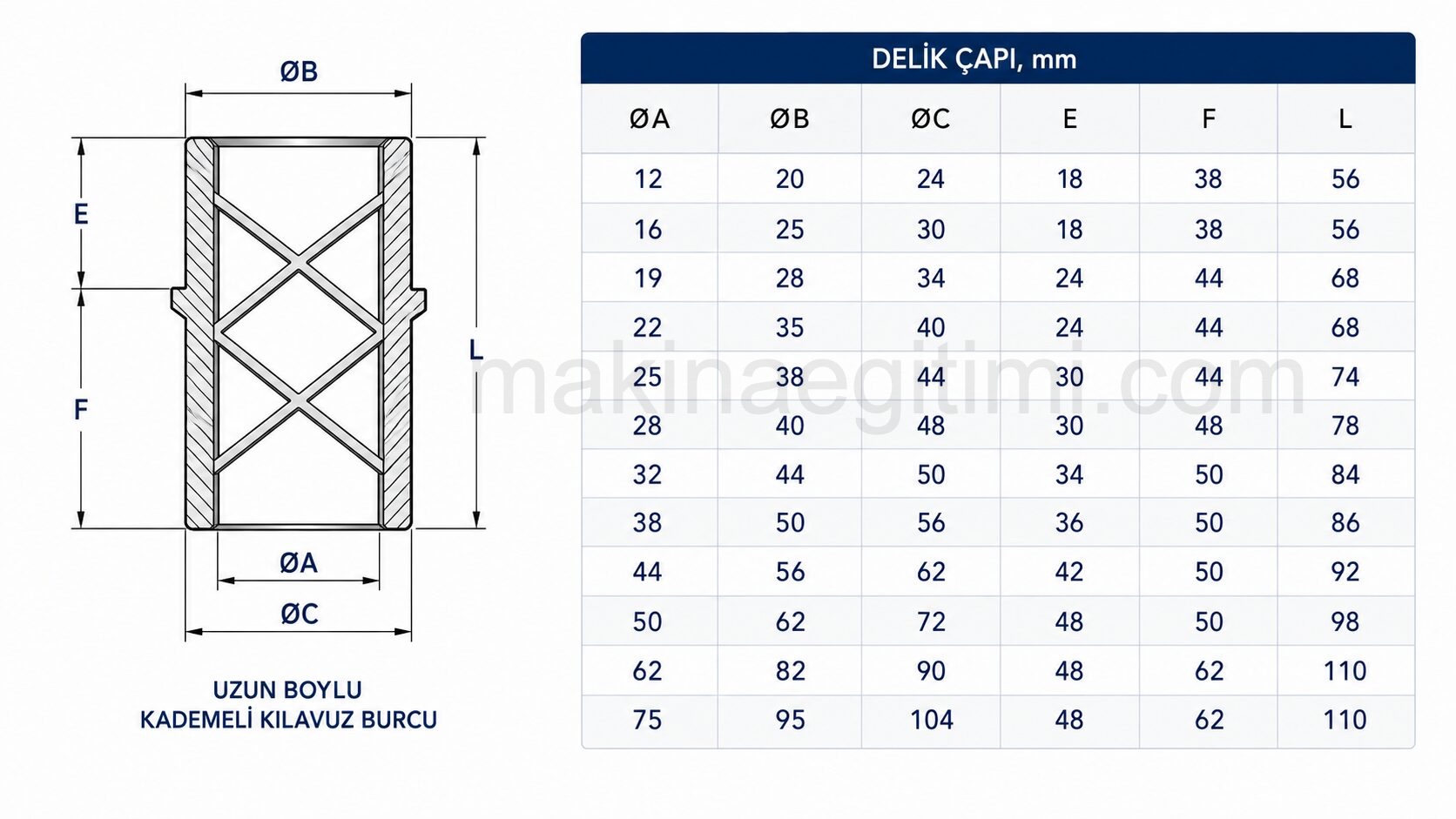
Die Guide Bushings





Assembling the Guide Pillars and Bushings
The guide pillar dimensions used in a die set are determined by a strength calculation based on the die’s capacity and dimensions. Standard die set manufacturers have also standardized the dimensions of the guide pillars and bushings used with the dies they produce.
The most commonly applied guide pillar diameter ranges from 25 mm to 75 mm. The guide pillar’s length must not extend past the surface of the upper die plate when the die is closed.
Related Posts