
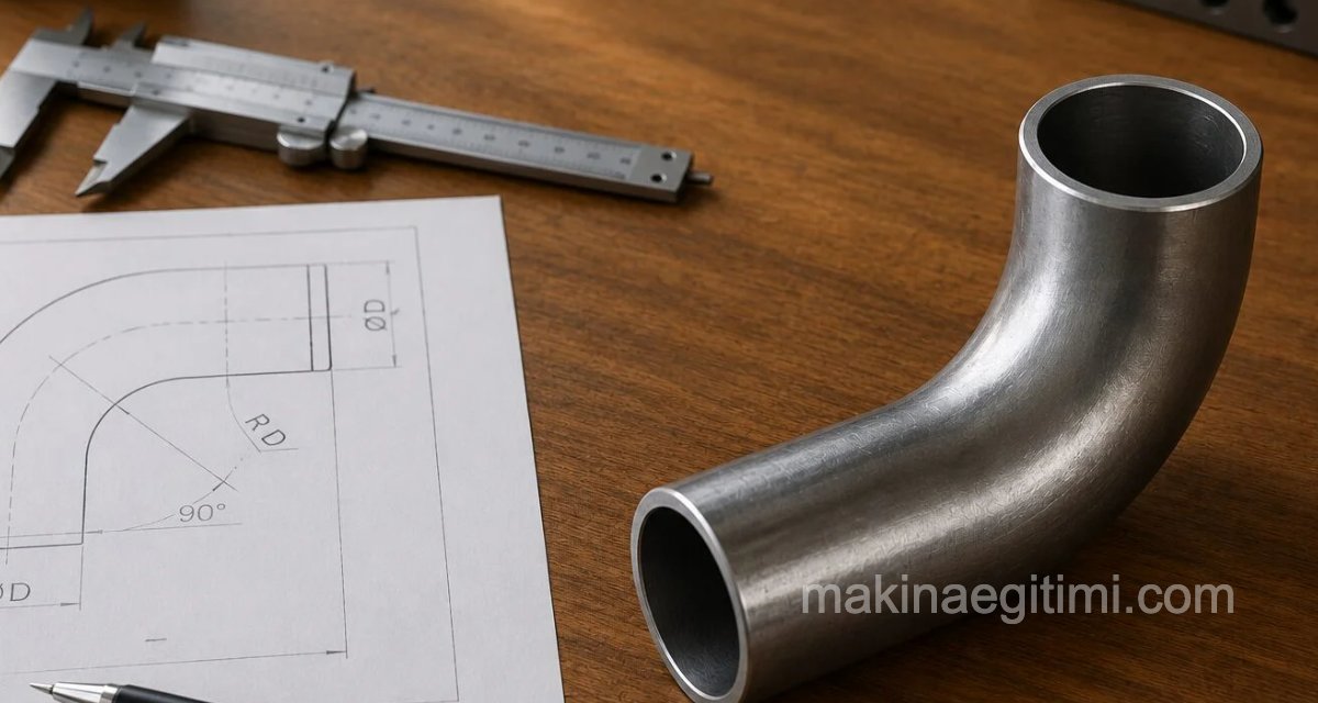
The bending stress of sheet metal materials is similar to the bending stress in beams. For this reason, the bending moment formula for beams is applied to the bending force of sheet metal materials in exactly the same way. The figure below shows a beam subjected to bending.

Mo = P x L, kg·cm (bending moment about point “o”)
I = b x h3 / 12 (beam moment of inertia)
For detailed information on moment
see: What Is Moment, How Is It Calculated. Lesson

When strip material width (W) is substituted for beam width (b), and strip material thickness (T) is substituted for beam thickness (h), the following bending force formula is obtained.
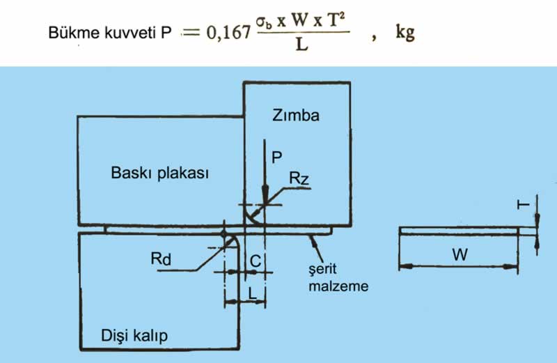
In simple bends, the distance (L) between the bending force and the support point is found with the following formula.
L = Rd + Rz+ C (mm)
P = Bending force, kg
W = Strip material width, mm
T = Strip material thickness, mm
C = One-sided die clearance, mm
Rd = Die radius, mm
Rz = Punch nose radius, mm
σb = Bending stress of strip material, kg/mm²
The one-sided die clearance (C) based on strip material thickness is given in the table below.
| Strip material thickness T (mm) | One-sided die clearance C (mm) |
| – 0.50 | (1.08 – 1.10 ) T |
| 0.50 -1.25 | (1.09 – 1.12 ) T |
| 1.25 – 3.25 | (1.12 – 1.14) T |
| 3.25 and above | (1.15 – 1.20 ) T |
Table of one-sided die clearance (C) based on strip material thickness (above)
NOTE: The constant coefficient of 0.167 applied in the bending force formula given above is taken as 0.333 if the distance (L) between the centers on which the bending force acts decreases.
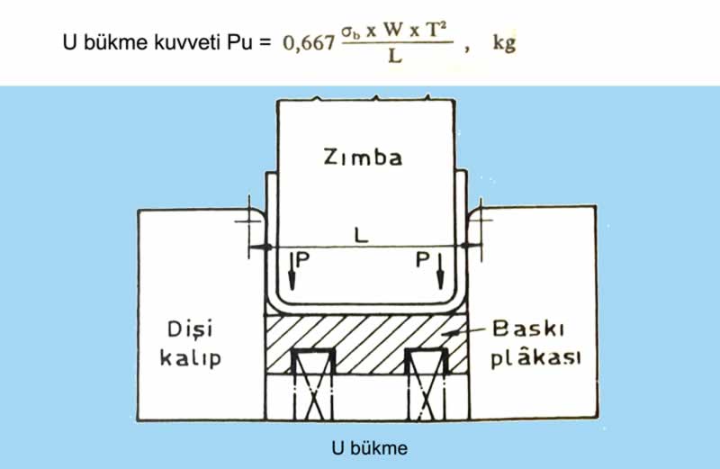
For “U” or channel bends, the constant coefficient is taken as 0.667. Accordingly, the “U” bending force is written as follows.
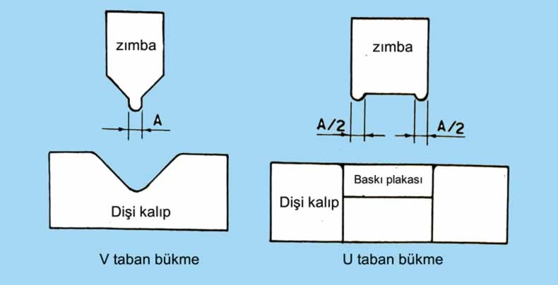
For V-bend dies, the coefficient is taken between 1.2 and 1.33.

For flattening (coining/base) bends, the coefficient is taken as (1). In a flattening bend, the bending force is found by multiplying the punch tip width (flattening bend width), the strip material width, and the tensile strength of the strip material.
Flattening bend P = σb . W . A
A = Flattening bend or punch tip width, mm
The table below gives the bending stresses of some materials. The bending stress of the part to be subjected to the bending operation is taken from this table.
| Material Type | Bending Stress σb (kg/mm²) |
| Aluminum and its alloys | 10 – 60 |
| Brass | 20 – 60 |
| Zinc | 15 – 20 |
| Copper | 25 – 38 |
| Bronze | 48 – 72 |
| Steel | 34 – 62 |
| Stainless steel | 30 – 62 |
Bending dies are generally made with a pressure plate. In this type of die, the pressure force can be provided by a spring or rubber pad, as well as by pressure plates operated with a pneumatic (compressed air) or hydraulic system.
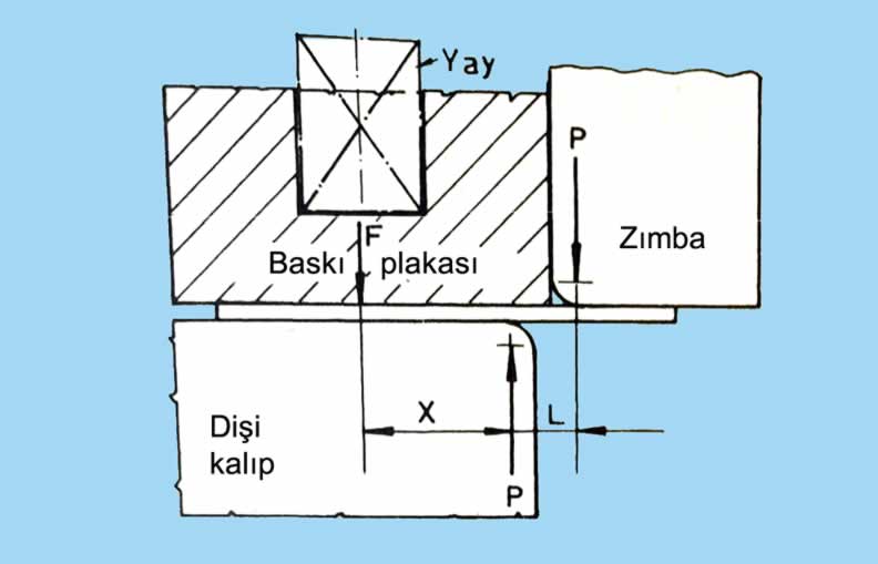
To find the pressure plate force, bending force (P) times moment arm (L) is set equal to pressure plate force (F) times moment arm (X).
Pressure plate force = P . L / X (kg)
F = Pressure plate force, kg
X = Distance between the pressure plate force’s center and the moment center, mm
Bending Force Calculation – Worked Example 1

The part whose dimensions are given is to be bent 40 mm wide from 3 mm thick brass material. Since this part will be produced in a production run,
Find the U-bending force.
Design the U-bending die.
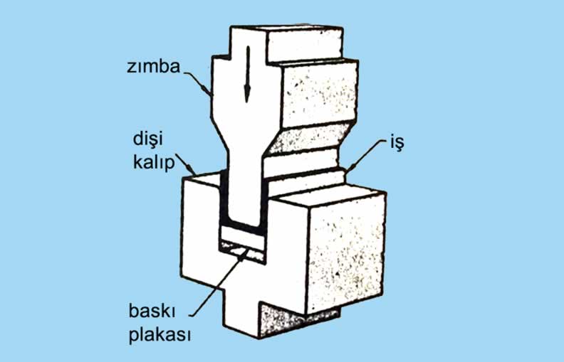
Solution
U-bending force: Pu = 0.667 . σb . W . T² / L
From the bending stress table above, σb = 30 kg/mm²
W = 40 mm
L = 42 mm
T = 3 mm, so
Pu = 0.667 . 40 . 3² / 42
Pu = 171.5 kg
We previously covered the calculation of the flat-pattern (blank) length for this same bent workpiece — see: Bend Length Calculation for Bending Dies. Feel free to take a look if you’d like.
Bending Force Calculation – Worked Example 2

The part whose dimensions are given is to be 90° V-bent, 50 mm wide, from 2 mm thick aluminum material. Since this part will be produced in a production run;
Find the bending force?
Design the V-bending die.
Solution
Pv = 1.33 . σb . W . T² / L
W = 50 mm T = 2mm L = 2mm
From the table: σb = 10 kg/mm²
Pv = 1.33 . 10 . 50 . 2² / 56
Pv = 47.5 kg

Related Posts
 Blank Diameter Calculation in Drawing Dies
  Compression Molds and Their Types
  Drawer Rail Piercing Die Assembly and Detail Drawings
  Rectangular or Square Drawing Dies
  Deep-Drawing Dies
  Mold Making With the Selective Laser System
  What Is Aluminum Extrusion, How Is It Done?
  Plastic Injection Molds: Injection System