To prevent wrinkling of the part material during drawing and to determine which type of die it should be drawn in, the ratio of sheet thickness to blank diameter is calculated in advance. This ratio is found as a percentage (%) using the formula below.
Ratio of sheet thickness to blank diameter: T/D x 100
D = Blank diameter of the part to be drawn, mm
T = Sheet material thickness, mm
The following points should be considered to prevent wrinkling of the part being drawn.
- If the ratio of sheet thickness to blank diameter, T/D x 100 or %T/D, is equal to or less than 0.5, the tendency to wrinkle is high. For this reason, drawing is done in a double-action die with a blank holder.
- If the ratio of sheet thickness to blank diameter, T/D x 100 or %T/D, is between 0.5 and 1.5, the tendency to wrinkle will be lower than in the first case. However, to draw safely, a double-action drawing die with a blank holder is still used.
- If the ratio of sheet thickness to blank diameter, T/D x 100 or %T/D, is between 1.5 and 2.5, the tendency to wrinkle will be low, so drawing is done in a single-action die without a blank holder.
- If the ratio of sheet thickness to blank diameter, T/D x 100 or %T/D, is equal to or greater than 2.5, no wrinkling will occur, so no blank holder is used and drawing is done in single-action dies.
Determining How Many Stages the Drawing Should Be Done In
The percentage (%) reduction between diameters is calculated to determine how many stages the drawing process can be done in.
The percentage reduction between diameters is found with the formula below;
Percentage reduction between diameters = (D – d) / D x 100
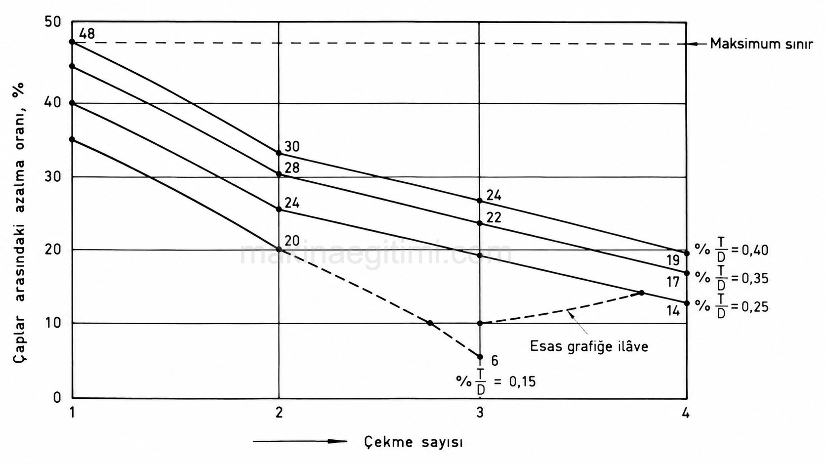
In general, on the first draw, the percentage (%) reduction between diameters should be kept between 30% and a maximum of 50%. For the first draw, an average percentage reduction between diameters of around 40% is used. For each subsequent draw, the percentage reduction between diameters should be taken as 25% less than the previous ratio.
The figure below shows the relationship diagram between the percentage reduction between diameters, the ratio of sheet thickness to blank diameter, and the number of draws for a part to be drawn from aluminum 3030 material.
The percentage (%) reduction between diameters for a part to undergo more than one drawing operation is found with the formula below.

dn = The final drawn diameter, mm
d(n-1) = The diameter of the draw before the final draw, mm

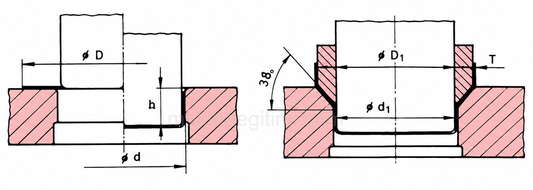
The figure above shows the diameter relationship diagram for parts to be drawn from medium-carbon steel sheet up to 3 mm thick.
Worked Example
A cylindrical container with a diameter of 50 mm and a depth of 60 mm is to be drawn from carbon steel sheet with a thickness of 1 mm. Calculate the blank diameter and find the drawn diameter at each stage from the diagram above.

From the diagram above, the first draw diameter is d = 72 mm, the second draw diameter is d1 = 56 mm, and the final draw diameter will be drawn to the specified dimension (50 mm).

The chart above gives the ratio of sheet thickness to blank diameter and the percentage (%) diameter reduction on the first draw for low- and medium-carbon steel materials.
Related Posts