

CNC Lathe Setup Instructions
A – STARTING UP THE MACHINE;
1- Turn on the main switch. (Located at the back of the machine.)
2- Turn the CNC OFF – ON key and hold it for a few seconds. (Located at the far right rear of the panel.)
3- Press the hydraulic button to start it. (Second button from the bottom on the right side of the panel.)
4- Send the machine to reference (home). (ZRN, first in the X+ then in the Z+ axis.) NOTE: If it doesn’t go to reference, perform a recovery from the limit switch. (The hydraulic motor may have stopped.) Hold down the hydraulic button and move it with X- or Z-.
B – MEASURING THE TOOL
1- Switch to MDI mode, type in the tool number, and press start.
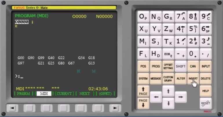
2- To reference the chuck, type M19 and press start. (It rotates to the chuck and references; if it doesn’t, the chuck jaws are not open — open them by pressing the pedal.)
3- To lower the measuring arm; type M62 in MDI and press start.
To raise the measuring arm; type M63 in MDI and press start.
4- To Bring the Measuring Arm Close to the Cutter; switch to handwheel mode (HND) and bring the cutter to within about 5 mm of the arm’s tip corner using X- and Z-.
5- To Zero the Lathe Tools; in MDI mode type G21 T1.H3. and, going to the start of the line, press start. (While pressing start, enter the X and Z values on the Offset – Geom page.)
6- For the Drill; type G124 T7.H7. (To zero the Z axis.)
Type G124 T7.H8.C10 (10 = drill diameter) (To zero the X axis.)
Bring it to within 5 mm in both X and Z.
NOTE: Program No. 1000 has the tool-measuring program saved, and No. 1001 has the drill/tap-referencing program saved; you can use these.
C- MEASURING THE TOOL
- First, clamp the workpiece.
- Then touch the cutter to it in the Z axis.
- Then touch the cutter to it in the Z axis.
- Then face off or bring the cutter into contact.
- Then open the Offset – Work page.
- Go down to the G54 line below.
- Finally, finish zeroing the workpiece by typing Z0 and clicking the measure button
- X will always be 0
D- SIMULATION ON THE MACHINE SCREEN;
1- First press CSTB/CR (the key above the up-arrow key)
2- After this, the word GRAF will appear on the screen. Select MEM (Automatic) and press start. (Run the program with the workpiece clamping empty, approaching with controlled feed, to perform the simulation.)
Related Posts
 The World’s Most Modern CNC Machines Video Series
  G00 Rapid Positioning Without Cutting CNC Code
  Powering On a Fanuc CNC Lathe. How Is a CNC Lathe Powered On
  G01 Code. Linear Motion with Cutting
  CNC Lathe G84 Tapping Cycle Explained
  CNC Lathe Programming Examples
  Fanuc CNC Error Codes – Fanuc Fault Codes
  G75 CNC Grooving Cycle Code Explained