

In this article, we’ll cover the structure of CNC milling machines, including topics such as ways and slides, and the spindle.

Ways and Slides

The systems that provide the movement of the machine table and support the machine table are called ways and slides.
On conventional machines, table movements are provided by hand or by an electric motor, while on CNC machines, machine movements are performed by special servo motors controlled by a computer.


On conventional machines, square or trapezoidal (Acme) screws are used on the main shafts to move the table and carriage. However, the clearance between the screw and the nut cannot be avoided. Since the operator is aware of this, they take up the clearance by hand before starting to feed the cut.
Additionally, friction between the nut and shaft screw surfaces is high. Since all movements on CNC machines are performed by the computer, this clearance must not exist. On CNC machines, instead of square and trapezoidal screws, ball bearing screws are used, so motion is achieved through rolling friction instead of sliding friction, minimizing the amount of friction, and point contact friction is achieved instead of the surface friction found on conventional machines. This is illustrated in the figure
Slide Precision
Linear ways are ground to provide micron-level positioning precision in axis movement.
Lubrication System
Ways and slides are usually lubricated at regular intervals by an automatic central lubrication system to prevent wear.
Spindle Speed
The spindle can reach speeds ranging from a few hundred RPM up to 20,000 RPM, depending on the material and machining type.
CNC Milling Machine Spindle

The part on CNC milling machines that provides the rotary motion of the cutter is called the spindle. The spindle houses belt and pulley systems, coolant units, and the electric motor.
The machine’s spindle carries a very important design characteristic.
The spindle needs to be resistant to bending and torsion, and strong enough to withstand all axial forces acting along its axis. For this reason, the spindle must be very well supported and designed and mounted with a construction that will absorb (dissipate) vibration. Insufficient support causes not only dimensional errors but also poor surface quality and vibration.
Control Panel
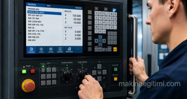
The control panel of a CNC milling machine is the main user interface where the machine’s operating commands are entered, programs are managed, and the machining process is monitored. The operator can load, edit, and run CNC programs through this panel. Additionally, many parameters, such as tool movements, spindle speed, feed rate, and the machine’s operating mode, are controlled via the panel.
The control panel generally includes sections such as a screen, keyboard, direction keys, operating mode selectors, feed and speed override settings, an emergency stop button, and a manual pulse generator (MPG) handwheel. The layout of these buttons and functions can vary depending on the machine’s model and CNC control unit.

The screen shows coordinates, the active program, tool information, spindle speed, and various operating states. The keyboard and softkeys are used for entering programs and parameters. The direction keys and handwheel enable the axes to be moved, especially during manual operation. The feed rate override and spindle speed override buttons allow the operator to adjust the feed rate and spindle speed specified in the program by a certain percentage.
The emergency stop button on the panel is a safety component that allows the machine to be stopped in an emergency. In addition, there may be control buttons for auxiliary functions such as coolant, chip conveyor, lubrication, and lighting.
Related Questions
With a square or trapezoidal screw, the shaft and nut surfaces move by sliding against each other, creating clearance between them. With a ball screw, since the balls move by rolling, friction and clearance are much lower, which increases precision.
On a conventional machine, the operator can feel and compensate for this clearance by hand. Since a computer controls the movement on a CNC machine, this kind of clearance silently causes a deviation between the programmed dimension and the actual machined dimension.
Related Posts
 CNC Longitudinal Turning Cycle – G90 – G71 – G70
 CNC Milling Workshop Operating Instructions
 Powering On a Fanuc CNC Lathe. How Is a CNC Lathe Powered On
 CNC G Code List and Meanings (Beginner’s Guide)
 CNC Lathe Setup Instructions
 CNC Lathe G84 Tapping Cycle Explained
 G00 Rapid Positioning Without Cutting CNC Code
 G01 Code. Linear Motion with Cutting