Close Menu
  • MAKİNELER ve İMALAT
    • Tools & Equipment
    • Computer-Aided Drawing
    • CAD/CAM Education
    • CNC Machine Programming
    • Casting Technologies
    • Electrical & Electronics Technologies
    • Hydraulics & Pneumatics
    • Manufacturing Processes
    • Manufacturing Technologies
    • Occupational Safety
    • Mold & Die Design
    • Solid Modeling
    • Welding Technology
    • Machine Elements
    • Mechanical Trade Drawing
    • Materials Science
    • Automotive & Vehicle Technologies
    • Robotics Technologies
    • Health Technologies
    • Defense & Aerospace Technologies
    • Descriptive Geometry
    • Technical Drawing
    • Software & Hardware Technologies
    • Innovative Manufacturing Methods
  • TEKNOLOJİ ve YAŞAM
    • OTOMOBİLLER ve TAŞIT
      • Vehicle & Engine Knowledge
      • Safe Driving
      • Sürüş Destek Sistemleri
    • Genel Kültür
      • Movies & TV Shows
      • Görsel ve Grafik Sanat
      • Books & Literature
      • Music
      • Sports
      • History
      • History of Technology
    • GÜNDELİK YAŞAM TEKNOLOJİLERİ
    • Hobbies & Entertainment
    • Internet Technologies
    • Health
    • Mobile Technologies
Makine Eğitimi
  • Machines & Manufacturing
    Machine Elements
    Hydraulics & Pneumatics
    Technical Drawing
    Computer-Aided Design & Manufacturing
    Basic Manufacturing Processes
    Manufacturing Processes
    Industry Technologies
    Other Technical Courses
    Motion & Power Transmission
    Simple Machines
    Chains & Sprockets
    Shafts & Journals
    Gears
    Cams
    Couplings
    Belts & Pulleys
    Springs
    Bearings
    Keys
    Fastening Joining
    Retaining Rings
    Screws, Bolts & Nuts
    Cotter Pins
    Flanges
    Welding
    Rivets
    Pins & Bolts
    Washers
    Calculators
    Gear Ratio Calculator
    Spring Constant Calculator
    Belt Pulley Ratio Calculator
    Other Machine Elements
    Slides & Linear Guides
    Brakes
    Flywheels
    Clamps
    Shock Absorbers
    Gaskets & O-Rings
    Seals & Sealing Elements
    Hydraulics
    Introduction to Hydraulics & Principles
    Hydraulic Systems & Applications
    Accumulators
    Filters
    Motors
    Pumps
    Valves
    Pneumatics
    Introduction to Pneumatics & Principles
    Pneumatic Systems & Applications
    Pneumatic Circuit Components
    Valves
    Cylinders
    Silencers
    Motors
    Compressors
    Dryers
    Conditioning Units
    Common Topics & Maintenance
    Hydraulic & Pneumatic Maintenance
    Study Notes, Exams & Tests
    Technical Drawing
    Introduction to Technical Drawing
    Geometric Drawings
    Perspective & Projection
    Orthographic Views
    Dimensioning
    Sectioning
    Assembly & Detail Drawings
    Tolerances
    Surface Finish Symbols
    Mechanical Engineering Drawing
    Screws, Bolts & Nuts
    Pulley Drawings
    Gear Drawings
    Shafts & Journals
    Bearing Drawings
    Pins & Bolts
    Spring Drawings
    Welds in Technical Drawing
    Washers
    Cotter Pins
    Technical Drawing Exercises
    Mechanical Drawing Exercises
    Gear Exercises
    View Extraction Exercises
    Pulley Exercises
    Pin & Bolt Exercises
    Threaded Fastening Exercises
    Descriptive Geometry
    Computer-Aided Drawing
    AutoCAD Drawing Lessons
    Computer-Aided Drawing Exams
    Solid Modeling & Animation
    Solid Model Drawing Files
    Solid Model Assembly Examples
    Solid Model Drawing Lessons
    3D CAD Software Reviews
    Solid Modeling Exercises
    CNC Programming
    CAM
    Measurement & Inspection
    Dial Indicators
    Calipers
    Gauges
    Micrometers
    Materials Science
    Steels
    Cast Iron
    Aluminum
    Plastics
    Material Testing & Hardness Measurement
    Occupational Safety
    Workshop Safety
    Safety When Working With Electricity
    Machine Safety Rules
    Hand Operations
    Filing
    Marking
    Cutting Operations
    Reaming
    Tapping
    Threading With a Die
    Drill Bit Sharpening
    Working With Machines
    Basic Turning Operations
    Basic Milling Operations
    Shaper Machine
    Machining
    Turning
    Milling
    Grinding
    Innovative Manufacturing Methods
    EDM (Electrical Discharge Machining)
    Laser Machining
    Waterjet Machining
    3D Printing
    3D Scanners
    Welding
    Rolling
    Casting
    Mold & Die Design
    Mechanical & Hydraulic Presses
    Blanking & Piercing Dies
    Bending Dies
    Drawing Dies
    Plastic Injection Molds
    Extrusion Dies
    Compound Dies
    Progressive Dies
    Blow Molds
    Spinning Dies
    Spray Molds
    Manufacturing of Machine Parts
    Automotive & Vehicle Technologies
    Motor Vehicle Manufacturing
    Raw Material Production
    History of Technology
    Health & Medical Technologies
    Defense & Aerospace
    Robotics Technologies
    Software & Hardware Technologies
    Mechanics - Strength of Materials
    Physics Topics
  • Technology & Life
    Hobbies & Entertainment
    Sports
    Music
    Vehicle & Engine Knowledge
    Vehicle Maintenance & Repair
    Safe Driving
    Driver Assistance Systems
    History
    Movies & TV Shows
    Books & Literature
    Computers & Internet
    Computer Tips
    Software Reviews
    Hardware & Peripherals
    Practical & Safe Internet Use
    Visual & Graphic Art
    Mobile Technologies
    Travel
    Science
    Health
    First Aid Knowledge
    Everyday Technologies
Makine Eğitimi
Home»CAD/CAM Education»What Is iMachining, Advanced CAD/CAM CNC Machining Technology
30 August 2026

What Is iMachining, Advanced CAD/CAM CNC Machining Technology

download imachining solidcam

What Is iMachining?

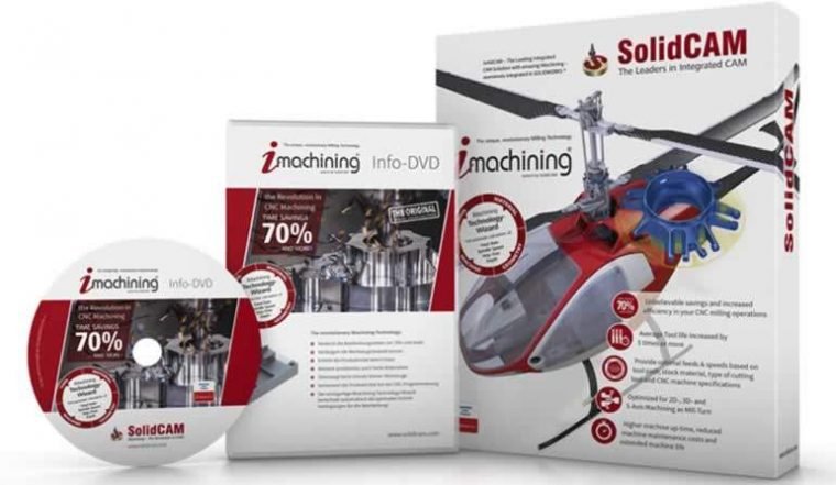
iMachining is a toolpath optimization technology developed by Solidworks, developer of major patented projects in 3D design and manufacturing well known to most of us, and by Dassault Systemes, the maker of 3D design programs like Catia. It reduces cutting times by 2-3 times, increasing your manufacturing efficiency. Without requiring any special equipment, it lets you make faster, deeper, and more efficient cuts using the tools and equipment you already have.
  • What Is iMachining?
  • Advantages of iMachining Technology
  • How Does iMachining Work?
    • Divide and Conquer Strategy
  • iMachining 3D on Prismatic Parts
    • Holder Collision Avoidance
    • Automatic Protection for the Target Model in Confined Spaces
download imachining solidcam
iMachining technology works fully compatibly with Solidworks, SolidCAM, Autodesk Inventor CAM, and Siemens NX.

Advantages of iMachining Technology

  • Saves 70% or more machining time.
  • Reduces the number of passes by machining deeper.
  • With remaining-stock calculations and finish-cut calculations, idle traversal moves are eliminated, keeping the tool continuously engaged in the cut without unnecessary retractions.
  • By using the tool’s full cutting-edge length, it distributes the load that would otherwise fall solely on the tool tip across the entire tool as it should be. This way, the tool doesn’t dull quickly.
  • With fully optimized feed rates and cutting speeds, it extends cutting tool life by an average of 5 times or more.
  • No need for advanced, specialized tooling when machining hard materials.

How Does iMachining Work?

The iMachining Technology Wizard uses an advanced, patented “technology algorithm” that automatically generates optimized feed, speed, depth, and width of cut.
It also uses CNC machine characteristics as well as stock and tool material properties to calculate and maintain the most suitable cutting conditions.

imachining wizard
iMachining wizard

Using the patented “Controlled Step Over” technology, iMachining ensures the toolpath strictly maintains the cutting conditions set by the Wizard.

With automatic feed and cutting speed calculation, trial-and-error costs are eliminated. Optimum, most efficient cutting is guaranteed on the very first part.

Divide and Conquer Strategy

One of the secrets behind iMachining boosting machining efficiency: the divide-and-conquer tactic

To clear pockets containing islands in the most efficient way, iMachining uses a patented division strategy, splitting the pocket into smaller regions and machining it as efficiently as possible.
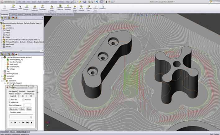
imachining technology
iMachining maximizes speed using its patented division strategy

This strategy creates the most efficient areas for spiral toolpaths. When moving from one position to another on the toolpath, it removes material even during positioning by always keeping the tool engaged in the chip.

Machining the ski goggle mold pictured above takes only 5 minutes with this technology. You can watch it in the video below.

Thanks to Controlled Step Over technology, iMachining promises that even the most complex parts can be finished in the shortest possible time. Let’s continue with the video below.

While in 2.5-axis programming the user has to individually select depths and chains, in iMachining 3D programming, geometry and depths are determined automatically from the 3D model, so no time is wasted.
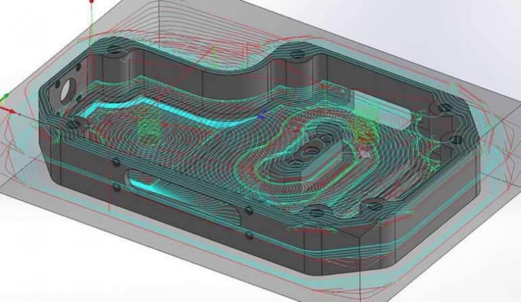
imachining cam advantages

Using Controlled Step Over technology and generating ideally scanned toolpaths, it completes Rough and Rest-Roughing operations in a single pass, preparing the part in the most optimal way for finishing operations.

A look at manufacturing a space shuttle part with iMachining

iMachining 3D on Prismatic Parts

When machining prismatic parts, iMachining 3D automatically maximizes performance and efficiency to achieve the shortest machining time.

In this system, the tool starts removing material from the deepest point it can reach first, thereby achieving maximum material removal with the most suitable depth and step-over. While the material removal rate and tool life are calculated at the highest possible level, retractions and idle travel are minimized.

For Z-level regional cuts, it optimally calculates areas close to each other and performs the regional cuts in an ideal, sequential order. Idle travel moves are avoided thanks to 2D regional toolpaths and smart 3D Z-level movements.

imachining 3d

It automatically identifies all pockets at different depths and levels using the Pool Recognition feature. This minimizes programming time and completes the cut in a single operation.

Holder Collision Avoidance

In every operation, iMachining 3D continuously optimizes toolpaths to prevent collision between the tool holder and the current stock.

Without the Collision Avoidance feature, the distance between the holder and the tool has to be unnecessarily extended in order to machine deep pockets and regions.
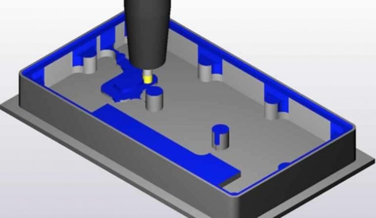
imachining cam prismatic parts

In this system, since the distance between the holder and tool is kept shorter, the shorter and stronger tool can work much faster and more aggressively. This is one of the secrets behind iMachining’s efficiency gains.

Automatic Protection for the Target Model in Confined Spaces

imachining 3d confined spaces

When machining in confined spaces with large tools, it automatically protects the target model to prevent contact with it.

DOWNLOAD SolidCAM and iMachining 30-Day Trial Version

Related Posts
cam computer aided manufactury Advantages of Computer Aided Manufacturing (CAM) autocad flywheel IGES What Is the IGES File Format, What Is It Used For? Catia ile Cam İşleme Örneği Şurup Kaşığı Dişi kalıp CAM Machining Example in CATIA – Syrup Spoon Female Die STEP Dosya Formatı Nedir, Ne İçin Kullanılır? What Is the STEP File Format, and What Is It Used For? What are CAD and CAM What Are CAD and CAM? What Are the Differences?
Share. Facebook Twitter WhatsApp Tumblr Email Telegram Copy Link

Leave A Reply Cancel Reply


What the Markings on a Car Tire Mean
How to Start Writing a Book? Advice Backed by Science
  • Contact
  • Terms of Service
  • Privacy & Cookie Policy

Type above and press Enter to search. Press Esc to cancel.