Close Menu
  • MAKİNELER ve İMALAT
    • Tools & Equipment
    • Computer-Aided Drawing
    • CAD/CAM Education
    • CNC Machine Programming
    • Casting Technologies
    • Electrical & Electronics Technologies
    • Hydraulics & Pneumatics
    • Manufacturing Processes
    • Manufacturing Technologies
    • Occupational Safety
    • Mold & Die Design
    • Solid Modeling
    • Welding Technology
    • Machine Elements
    • Mechanical Trade Drawing
    • Materials Science
    • Automotive & Vehicle Technologies
    • Robotics Technologies
    • Health Technologies
    • Defense & Aerospace Technologies
    • Descriptive Geometry
    • Technical Drawing
    • Software & Hardware Technologies
    • Innovative Manufacturing Methods
  • TEKNOLOJİ ve YAŞAM
    • OTOMOBİLLER ve TAŞIT
      • Vehicle & Engine Knowledge
      • Safe Driving
      • Sürüş Destek Sistemleri
    • Genel Kültür
      • Movies & TV Shows
      • Görsel ve Grafik Sanat
      • Books & Literature
      • Music
      • Sports
      • History
      • History of Technology
    • GÜNDELİK YAŞAM TEKNOLOJİLERİ
    • Hobbies & Entertainment
    • Internet Technologies
    • Health
    • Mobile Technologies
Makine Eğitimi
  • Machines & Manufacturing
    Machine Elements
    Hydraulics & Pneumatics
    Technical Drawing
    Computer-Aided Design & Manufacturing
    Basic Manufacturing Processes
    Manufacturing Processes
    Industry Technologies
    Other Technical Courses
    Motion & Power Transmission
    Simple Machines
    Chains & Sprockets
    Shafts & Journals
    Gears
    Cams
    Couplings
    Belts & Pulleys
    Springs
    Bearings
    Keys
    Fastening Joining
    Retaining Rings
    Screws, Bolts & Nuts
    Cotter Pins
    Flanges
    Welding
    Rivets
    Pins & Bolts
    Washers
    Calculators
    Gear Ratio Calculator
    Spring Constant Calculator
    Belt Pulley Ratio Calculator
    Other Machine Elements
    Slides & Linear Guides
    Brakes
    Flywheels
    Clamps
    Shock Absorbers
    Gaskets & O-Rings
    Seals & Sealing Elements
    Hydraulics
    Introduction to Hydraulics & Principles
    Hydraulic Systems & Applications
    Accumulators
    Filters
    Motors
    Pumps
    Valves
    Pneumatics
    Introduction to Pneumatics & Principles
    Pneumatic Systems & Applications
    Pneumatic Circuit Components
    Valves
    Cylinders
    Silencers
    Motors
    Compressors
    Dryers
    Conditioning Units
    Common Topics & Maintenance
    Hydraulic & Pneumatic Maintenance
    Study Notes, Exams & Tests
    Technical Drawing
    Introduction to Technical Drawing
    Geometric Drawings
    Perspective & Projection
    Orthographic Views
    Dimensioning
    Sectioning
    Assembly & Detail Drawings
    Tolerances
    Surface Finish Symbols
    Mechanical Engineering Drawing
    Screws, Bolts & Nuts
    Pulley Drawings
    Gear Drawings
    Shafts & Journals
    Bearing Drawings
    Pins & Bolts
    Spring Drawings
    Welds in Technical Drawing
    Washers
    Cotter Pins
    Technical Drawing Exercises
    Mechanical Drawing Exercises
    Gear Exercises
    View Extraction Exercises
    Pulley Exercises
    Pin & Bolt Exercises
    Threaded Fastening Exercises
    Descriptive Geometry
    Computer-Aided Drawing
    AutoCAD Drawing Lessons
    Solid Modeling & Animation
    Solid Model Drawing Files
    Solid Model Assembly Examples
    Solid Model Drawing Lessons
    3D CAD Software Reviews
    Solid Modeling Exercises
    CNC Programming
    CAM
    Measurement & Inspection
    Dial Indicators
    Calipers
    Gauges
    Micrometers
    Materials Science
    Steels
    Cast Iron
    Aluminum
    Plastics
    Material Testing & Hardness Measurement
    Occupational Safety
    Workshop Safety
    Safety When Working With Electricity
    Machine Safety Rules
    Hand Operations
    Filing
    Marking
    Cutting Operations
    Reaming
    Tapping
    Threading With a Die
    Drill Bit Sharpening
    Working With Machines
    Basic Turning Operations
    Basic Milling Operations
    Shaper Machine
    Machining
    Turning
    Milling
    Grinding
    Innovative Manufacturing Methods
    EDM (Electrical Discharge Machining)
    Laser Machining
    Waterjet Machining
    3D Printing
    3D Scanners
    Welding
    Rolling
    Casting
    Mold & Die Design
    Mechanical & Hydraulic Presses
    Blanking & Piercing Dies
    Bending Dies
    Drawing Dies
    Plastic Injection Molds
    Extrusion Dies
    Compound Dies
    Progressive Dies
    Blow Molds
    Spinning Dies
    Spray Molds
    Manufacturing of Machine Parts
    Automotive & Vehicle Technologies
    Motor Vehicle Manufacturing
    Raw Material Production
    History of Technology
    Health & Medical Technologies
    Defense & Aerospace
    Robotics Technologies
    Software & Hardware Technologies
    Mechanics - Strength of Materials
    Physics Topics
  • Technology & Life
    Hobbies & Entertainment
    Sports
    Music
    Vehicle & Engine Knowledge
    Vehicle Maintenance & Repair
    Safe Driving
    Driver Assistance Systems
    History
    Movies & TV Shows
    Books & Literature
    Computers & Internet
    Computer Tips
    Software Reviews
    Hardware & Peripherals
    Practical & Safe Internet Use
    Visual & Graphic Art
    Mobile Technologies
    Travel
    Science
    Health
    First Aid Knowledge
    Everyday Technologies
Makine Eğitimi
Home»CNC Machine Programming»CNC G Code List and Meanings (Beginner’s Guide)
30 August 2026

CNC G Code List and Meanings (Beginner’s Guide)

CNC G code list beginner guide

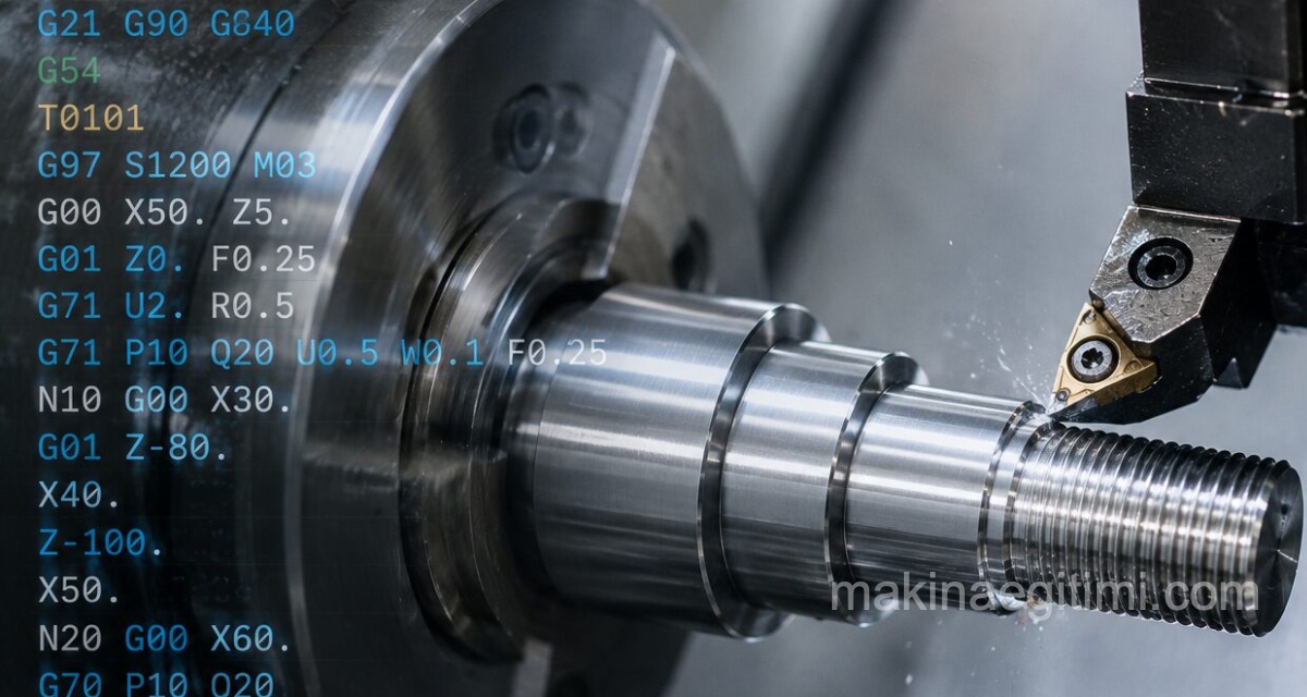
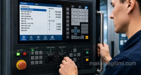
G and M codes form the foundation of programming CNC machines. These codes are a universal language that tells the machine commands like “go here,” “go this fast,” and “run this function.” In this article, we’ve compiled the most commonly used G and M codes, their meanings, and how they’re used with simple examples.

  • What Is a G Code?
  • Most Commonly Used G Codes
  • What Is an M Code?
  • A Simple Example Program
  • Things to Watch Out for When Learning G Codes
  • Conclusion

What Is a G Code?

G codes (Geometric/Preparatory Function) are commands that tell the CNC machine how the cutting tool should move. They define geometric movements such as linear motion, circular motion, and rapid positioning. Each G code activates a specific motion mode in the machine’s control unit, and that mode stays in effect until it’s changed by another G code.

Most Commonly Used G Codes

CodeMeaningDescription
G00Rapid positioningThe tool moves to the specified point at the fastest speed, without touching the workpiece.
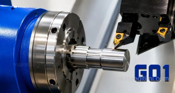
G01Linear interpolationThe tool cuts along a straight line at the specified feed rate.
G02Circular interpolation (clockwise)The tool cuts following a circular path in the clockwise direction.
G03Circular interpolation (counterclockwise)The tool cuts following a circular path in the counterclockwise direction.
G04DwellKeeps the tool stationary for the duration specified in the program.
G17/G18/G19Plane selectionActivate the XY, XZ, and YZ planes, respectively, for circular interpolation.
G20/G21Unit selectionG20 activates inch units, G21 activates millimeter units.
G28Return to reference pointSends the tool to the machine’s defined reference (home) point.
G40/G41/G42Tool radius compensationG40 cancels compensation, G41 activates left compensation, G42 activates right tool radius compensation.
G54-G59Workpiece coordinate systemUsed to define different workpiece zero points.
G90/G91Absolute / incremental programmingG90 defines coordinates relative to the zero point, G91 defines them relative to the previous point.
G92Coordinate system settingSets the tool’s current position to a specific coordinate value (lathe).

What Is an M Code?

M codes (Miscellaneous/Machine Function) deal not with the machine’s motion but with its auxiliary functions: spindle rotation, turning coolant on/off, stopping the program, and so on. While G codes say “how to move,” M codes say “which additional function to run.”

CodeMeaning
M00Stop program (manual resume)
M02End of program
M03Rotate spindle clockwise
M04Rotate spindle counterclockwise
M05Stop spindle
M06Tool change
M08Turn coolant on
M09Turn coolant off
M30End of program and return to start

A Simple Example Program

Below is a simplified example program written to mill a straight slot on a milling machine:

G21 G90 G17         (unit: mm, absolute coordinates, XY plane)
G54                  (workpiece coordinate system)
M03 S1500            (spindle clockwise, 1500 rpm)
G00 X0 Y0 Z5         (rapid move to start point)
G01 Z-2 F100         (plunge 2 mm into part, 100 mm/min feed)
G01 X50 F200         (50 mm linear cut)
G00 Z5                (raise the tool)
M05                   (stop spindle)
M30                   (end of program)

Things to Watch Out for When Learning G Codes

  • Most G codes can vary slightly depending on the machine’s control system (Fanuc, Siemens, Heidenhain, etc.); always check the programming manual for the control unit of the machine you’re using.
  • Before running a new program, always check it with a simulation or a “dry run.”
  • When moving rapidly with G00, make sure the tool doesn’t collide with the workpiece or fixtures.
  • Learn to distinguish between modal (persistent) and non-modal (single-line) codes; this saves a lot of time when reading code.

Conclusion

G and M codes are the basic alphabet of CNC programming. Learning these codes by understanding their logic, rather than memorizing them, lets you read programs generated by CAM software, spot errors, and make small manual edits when needed. Practicing by programming simple parts with the basic codes is the fastest way to progress in this field.

Related Posts
G01 Linear Motion with Cutting Cnc code G01 Code. Linear Motion with Cutting CNC Lathe Setup Instructions CNC Lathe Setup Instructions CNC Lathe Workshop Work Instructions CNC Lathe Workshop Work Instructions modern CNC machines video series The World’s Most Modern CNC Machines Video Series How Is a Fanuc CNC Lathe Powered On Powering On a Fanuc CNC Lathe. How Is a CNC Lathe Powered On CNC Facing Cycle CNC Facing Cycle – G94-G72-G70 Mechanical Clamping Elements on Machine Tools Mechanical Clamping Elements on Machine Tools download imachining solidcam What Is iMachining, Advanced CAD/CAM CNC Machining Technology
Share. Facebook Twitter WhatsApp Tumblr Email Telegram Copy Link

Leave A Reply Cancel Reply

Disc Brake & Drum Brake. Which Is Better?
From Book to Big Screen: How Was The Lord of the Rings Adapted?
  • Contact
  • Terms of Service
  • Privacy & Cookie Policy

Type above and press Enter to search. Press Esc to cancel.