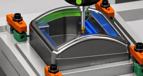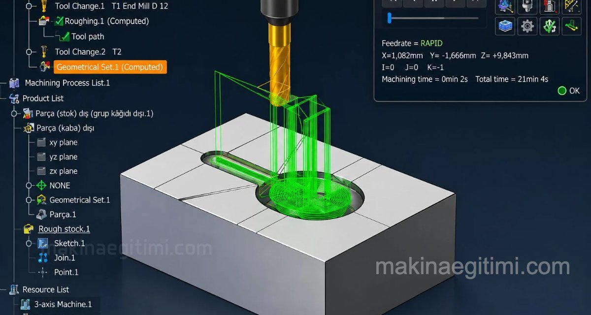
An example of using CAD/CAM with CATIA V5. Creating a female die toolpath in CATIA, simulation, and generating CNC code output.

After completing the stock-extraction operations on our part modeled in SolidWorks, it’s saved in “stepap203” format using the Save As option.

Right-clicking our saved file, we select CATIA from the “Open with…” option, opening our file in the CATIA environment.

The program then automatically converts the data, and our part is now transferred into the CATIA environment.

The view of our part opened in the CATIA environment…

Next, as one of the preparation steps, an auxiliary plane is assigned to set the safety distance our tool will retract to. “The value considered appropriate for this part is 50mm.”

The stock is defined for our part from the “Create Rough Stock” icon. The part is selected and OK is clicked.

A point is assigned to serve as the tool’s entry point.
Using the “Between” option, a point is placed exactly at the middle point of the two selected points. After these preparations, our part is now ready for the CAM environment.

After completing the preparation of our part, we switch to the CAM environment via “Start menu → Machining → Surface Machining.”
Double-clicking “Part Operation.1” brings up a dialog box where all the parameters needed for the part operation appear.

The name to give the part operation is entered in this field. (1)
You can write any notes you like in the “Comment” section. These notes will appear in the “apt” file with the “PPRINT” command. (2)

The machine type is selected from this area, “MACHINE.” (3)
The required axis definition for the part operation is created from “Reference Machining Axis System.” (4)

In the box that appears for the axis definition, the point at the exact center of the axis is marked, followed by marking the point we placed at the center of our part during preparation, and confirming (OK)

The “Part” selection is made for the part to be machined. (5)
The stock of our part is selected. (6)
The plane we assigned as the safe distance for our tool is selected in the “Safety Plane” section. (7)

With “Manufacturing Program” selected, (8)
click “Roughing” from the machining options. (9)

In the window that opens, select the part itself for “Part,” making that field turn green. (10)

The path the tool will follow during machining, and how much cutting will be taken with each plunge, is set here. (11)
Machining will proceed with a cut depth of 0.5mm per pass on the Z plane.

We make our tool selection in this section. If desired, it’s possible to pull a ready-made tool from the library. (12)
To move on to the calculation, click the “Tool Path Replay” button. (13)

The simulated view of the toolpaths — clicking the “Play” button lets you view the machining step by step.
With the “Video From Last Saved Result” option, we can also see a solid machining simulation on a stock part.

For the finish operation, using the same machining method, this time I set the pass depth to “0.1mm” and calculate the toolpath with the same tool, machining the remaining material. (14)

While the calculation continues, a dialog box on screen lets us see the progress (what percentage is complete, how many minutes remain, etc.).

The toolpath generated for the finish operation…

The simulation of our finished part…

After generating the toolpath for our part, we get the NC codes for this program. To do this, click “Generate NC Output In Batch Mode.” (15)

The control unit is selected in the “NC Code” section, and the Execute option is clicked. (16)

The NC codes generated to the specified location are automatically saved under the operation names. (17)

NC codes for the program named
“roughing”
SOURCE: Homework notes from the CNC Machines and Programming course, Die-Making Program, Uludağ University Higher School of Technical Sciences. Prepared by: Murat Yeşilbaş, Yavuz İlhan
Related Posts