Two of the most common abbreviations we hear in the modern manufacturing world are CAD and CAM. Although they’re often mentioned together, they actually represent two distinct processes. In this article, we explain what CAD and CAM mean, the difference between them, and how a part travels step by step from design to production.
What Is CAD?
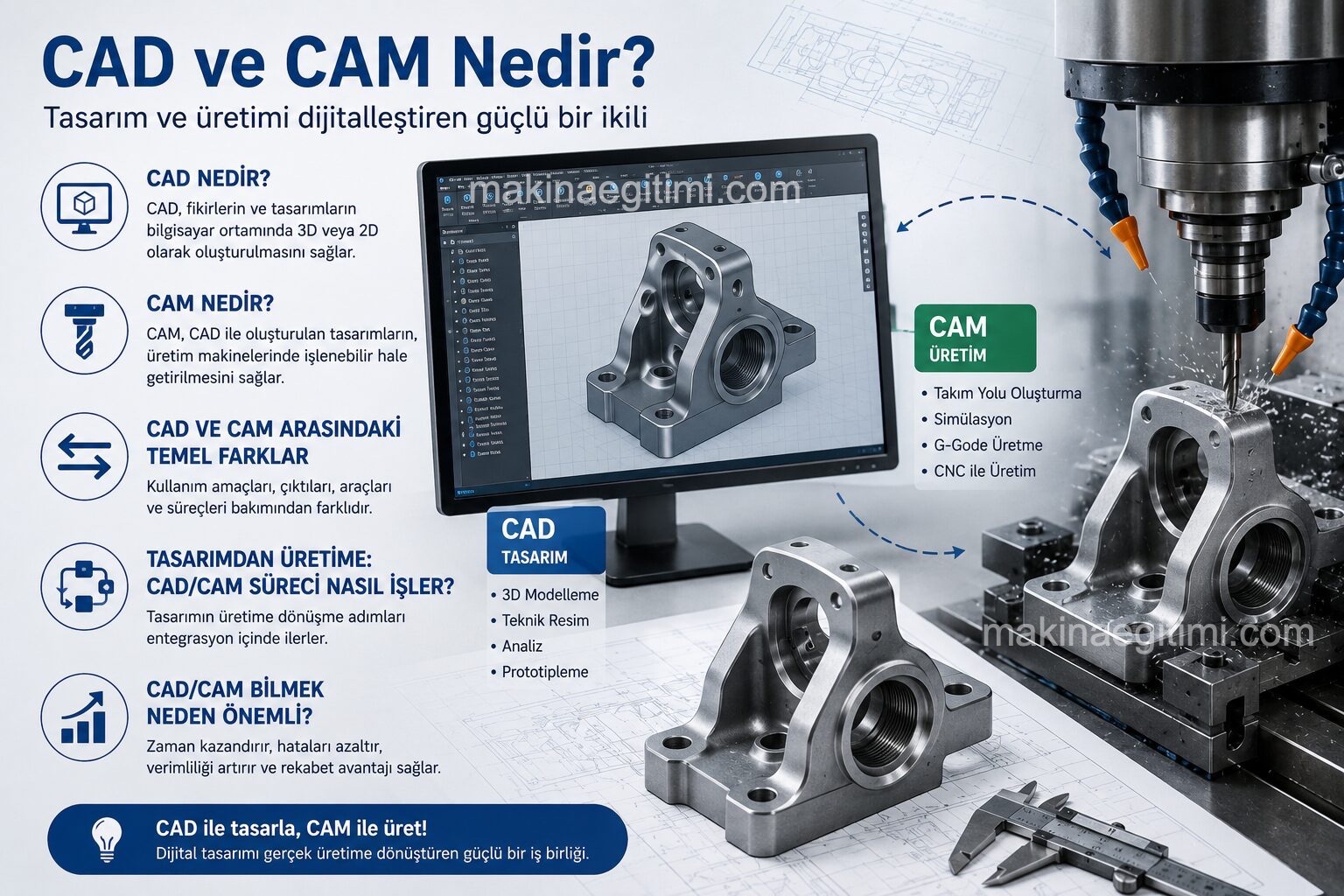
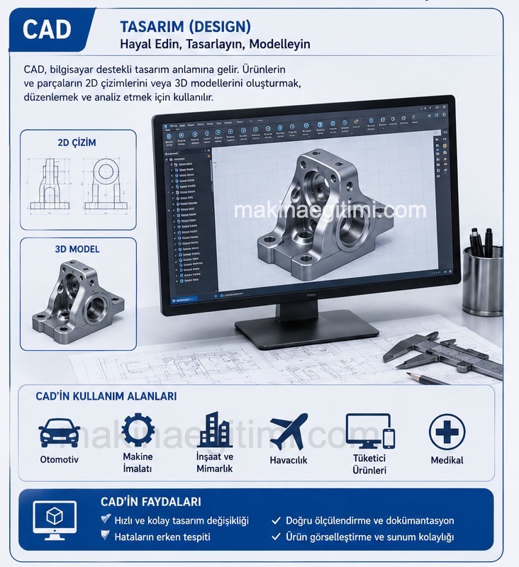
CAD (Computer Aided Design) is the general name for the software and methods that allow a part or product to be modeled in 2D or 3D in a computer environment. CAD software lets engineers and designers create dimensioned technical drawings, solid models, assembly diagrams, and simulations. SolidWorks, AutoCAD, Autodesk Inventor, Catia, and Fusion 360 are among the most widely used CAD programs.
The core purpose of CAD is to design an idea digitally—accurately, to scale, and editable—rather than on paper. Once a part’s 3D model has been created, dimensional changes can be made easily, assembly compatibility with other parts can be tested, and possible errors can be caught before actual production begins.

What Is CAM?
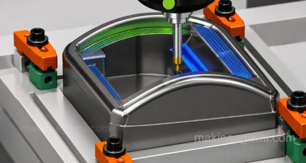
CAM (Computer Aided Manufacturing) refers to the software and methods that generate the tool paths and G-code programs needed to actually manufacture, on CNC machines, a model created in a CAD environment. A CAM program is fed the part’s 3D model, the cutting tools to be used, and the machining parameters (such as speed, feed, and depth of cut); the software then uses this information to produce a program (G-code) that the CNC machine can understand.
In other words, CAD defines “what we will produce,” while CAM defines “how we will produce it.” SolidCAM, Mastercam, the Fusion 360 CAM module, and SolidWorks CAM are among the best-known CAM programs.
Key Differences Between CAD and CAM
| Feature | CAD | CAM |
|---|---|---|
| Purpose | Design / modeling | Manufacturing / tool path generation |
| Output | 3D model, technical drawing | G-code / CNC program |
| User | Design engineer | CNC programmer / operator |
| Input | Idea, dimensions, requirements | CAD model, tool data |
| Example software | SolidWorks, AutoCAD | Mastercam, SolidCAM |
From Design to Production: How Does the CAD/CAM Process Work?

- 1. Design (CAD): The part’s 3D solid model is created, dimensioned, and its technical drawing is prepared.
- 2. Tool Path Generation (CAM): The CAD model is imported into the CAM software; cutting tools, machining strategy (roughing, finishing, etc.), and cutting parameters are determined.
- 3. Simulation: The generated tool path is simulated in a virtual environment before being run on the actual machine, checking for collision and error risks.
- 4. G-Code Generation: The CAM software converts the approved, simulated tool path into G and M codes that the CNC machine can understand (post-processing).
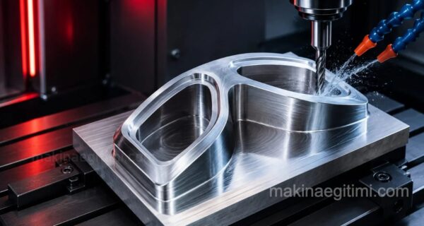
- 5. Production: The generated program is loaded onto the CNC machine and the actual part is machined.
Why Is Knowing CAD/CAM Important?
Today, nearly all sectors such as machine manufacturing, tooling/mold making, automotive, and aerospace operate on a CAD/CAM basis. Knowing CAD alone is enough to design a part, but knowing CAM lets you understand how that part will actually be machined on a real CNC machine.

For this reason, anyone who wants to work in machine technology, industrial design, or CNC programming gains a major advantage by learning both fields. In addition, CAM knowledge makes it possible to answer the question “can this part actually be manufactured?” earlier in the design stage, which also reduces production errors and costs.
CAD is the name for digitally designing a product; CAM is the name for creating the manufacturing instructions needed to turn that design into an actual part. The two are a natural continuation of one another and form an inseparable whole in modern manufacturing. CAD determines “what” will be produced, and CAM determines “how” it will be produced.
Related Posts