
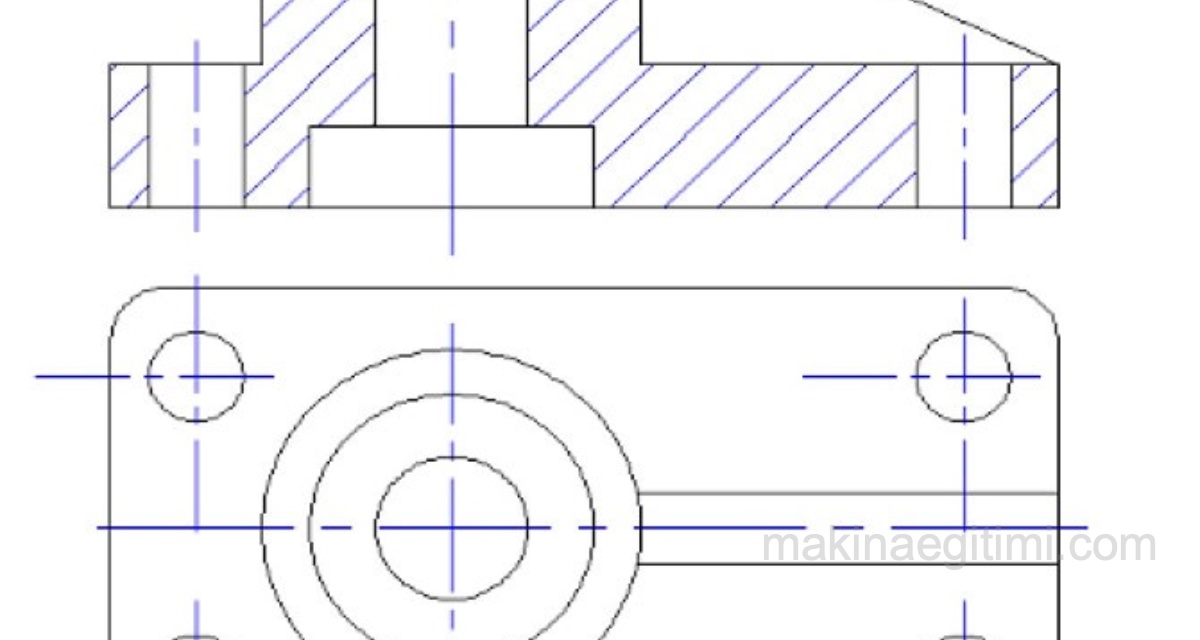
In the technical drawing lessons category, in this article, we’ll cover sectioning in technical drawing, the purpose of sectioning, how sectioning is done for complex parts with internal holes or cavities that work together and form a partial (sometimes full) assembly, the cutting plane, and the logic behind sectioning.
Sectioning
Many of us have tried opening up a machine that seemed complex to us to understand how it works. If we could see complex machines (like a car, for example) split in half, we’d understand how these machines work much better.

The sectioning topic we’ll cover here is exactly about this. Sectioning is perhaps the most enjoyable topic in technical drawing lessons. It appeals to and develops our imagination.
Purposes of Sectioning
Views in which an object is assumed to be cut, and its otherwise invisible interior sections are shown as visible, are called a “Sectional View.” In the “View Extraction” learning activity, we explained that when the views of a part to be manufactured are drawn, invisible areas remaining on the interior are drawn with thin dashed lines. Sectioning is performed so that these invisible details become visible, understandable, and can be dimensioned. This process is done only in our imagination and then transferred to the drawing. In other words, the part to actually be manufactured is not literally cut.
To make the structure of parts containing holes, grooves, etc. more understandable
If a part’s interior has holes or cavities, or its exterior has excessive protrusions and recesses, it’s difficult, sometimes even impossible, to represent parts of this type with one or a few views.

In such drawings, since the dashed lines drawn for invisible edges alongside the solid lines would cause confusion, understanding the part becomes difficult. For this reason, instead of drawing a picture full of dashed lines, a section of the parts is taken along a suitable plane (this is usually a plane of symmetry).

To make dimensioning easier
In the figure above, a perspective view of a spur gear is shown, along with the sectioning plane needed to dimension the gear’s elements. This way, when the spur gear is cut symmetrically right through its center, it will be much easier to show and dimension the gear’s hub, the keyway, the root diameter, and the tip diameter.
How Is Sectioning Done?
To take a section, as stated in the definitions, assuming a part is cut along a plane (or planes), the portion of the part in front of the cutting plane is discarded, and the orthogonal projection of the remaining portion onto that cutting plane is drawn.

Let’s say we have a part like the one above. When we look at the part isometrically from above and below, let’s say the views look like this.

If we wanted to draw this part without sectioning, a drawing like the one above would result. The excess of dashed lines and the difficulty of imagining the part’s shape stand out.
Step 1 in Sectioning
First, where the part to be sectioned will be cut is determined. The cutting plane is indicated as A-A as shown above.

When determining where to take the section, the aim is to reveal, as much as possible, the details that are difficult to understand with a normal drawing (such as holes, grooves, internal details).
Step 2 in Sectioning
Then, after the part is cut, the front half is removed so the cut surface becomes visible.
Step 3 in Sectioning
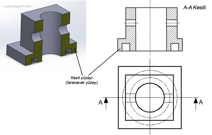
The front portion of the part is discarded, and with only the remaining portion left, the view perpendicular to the cutting plane of this portion is drawn. Regions cut by the cutting plane that are solid material are usually hatched with 45° hatching lines
In this drawing, all lines belonging to visible edges are drawn solid, and the regions cut by the cutting plane are hatched.
What Does the “A-A” Notation (Section A-A) Mean in Sectioning?
Sections are usually shown as front views. (as in the image above) In the top view, how and where the cutting plane divides the part is expressed with letters, in the form A-A. When taking a section, we assumed we separated the part with a large saw. The letters A-A here represent the two ends of the saw.
In technical drawing, it may not always be Section A-A. Sometimes, for complex parts, a second cutting plane may also be used, and in that case, the letters B-B are used for that cutting plane.
In stepped sections (cases where the cutting plane isn’t a straight line), a cutting plane expressed as A-B-C-D is also used. The topic of stepped sections will be covered in other articles.
In this article, we covered sectioning in technical drawing. We focused on details such as the purpose of sectioning, how sectioning is done, what a cutting plane is, and the logic behind sectioning. Since this article focused on the basic sectioning method, we didn’t cover methods other than the FULL SECTION method.
To examine other sectioning methods, see the Related Topics section
Related Topics
Related Posts
 Tolerance Terms and Their Meanings in Mechanical Engineering
  Technical Drawing Paper Sizes and Folding
  Hole and Shaft Tolerances
  Technical Drawing Instruments and Equipment
  Dimensioned Isometric Drawing Examples – Part 2
  Geometric Drawings 1 – Dividing Lines and Erecting Perpendiculars
  Dimensioned Isometric Drawing Examples – Part 1
  Choosing Tolerance Zones and Fits